
LiDAR-Based 3D Reconstruction for Robotic Pipelines Inspection
Monika Sara Kawka
1
, Lazaros Grammatikopoulos
1,2
, Ilias Kalisperakis
1
and Christos Stentoumis
1
1
up2metric, Michail Mela 21, Athens, Greece
2
Department of Surveying and Geoinformatics Engineering, University of West Attica, Agiou Spiridonos 28, Egaleo, Greece
{monika-sara.kawka, ilias, christos}@up2metric.com, lazaros@uniwa.gr
Keywords:
Robotics, LiDAR, Pipe Inspection, Computer Vision.
Abstract:
Robotic platforms have transformed pipe inspection from routine checks into an automatic data-driven pro-
cess. Such robotic systems often integrate computer vision technology to collect and analyze inspection data
in an automated and efficient way and offer additional capabilities such as 3D reconstruction of pipes and pre-
cise measurement of deformations (e.g., dents, buckling). This work presents an initial case study of a robotic
inspection system equipped with LiDAR and camera sensors capable of performing automatic pipeline in-
spections. This proof-of-concept study is dedicated to the 3D reconstruction of the pipeline using LiDAR data
collected during inspections. Reconstruction accuracy is evaluated by computing the RMSE for pipe surface
reconstruction and the deviation from the reference diameter of a single pipe in a controlled laboratory setting.
Reconstruction results reach an accuracy higher than 2cm based on computed RMSE and a precision higher
than 0.5cm in pipe diameter estimation. The current implementation is limited to the inspection of matte and
non-reflective pipes. Still, it offers a straightforward and scalable solution for various industrial sectors. Fu-
ture work will incorporate camera data to integrate color mapping into the 3D reconstruction model and detect
potential defects and deformations in a pipe.
1 INTRODUCTION
Robotic platforms are widely adopted, at least in the
research community, as an automated alternative to
traditional pipe exploration. Robust inspection re-
quires developing a robot that can adapt to various
pipe conditions and diameters, which remains an ac-
tive area of investigation (Kazeminasab et al., 2020;
Zhao et al., 2020; Ab Rashid et al., 2020; Elankavi
et al., 2022; Baballe et al., 2022). For the scope of
this work, such a robotic platform was developed;
however, in this contribution, emphasis is given on
sensors’ data fusion, the methodology employed for
3D reconstruction of pipelines in the form of point
clouds and estimating the actual diameter of pipes,
rather than on robot integration.
Visual information can enhance the automated
pipe inspection process and facilitate quick and direct
identification of the pipe’s interior features. In (Kako-
gawa et al., 2019) a camera-equipped pipe inspection
robot is used to perform shadow-based autonomous
navigation in straight and winding pipe. In (Gunati-
lake et al., 2021) two IR cameras are used for stereo
vision processing and reconstruction and one RGB
camera to map the color information to the recon-
structed 3D points. In (Tian et al., 2023), the visual in-
formation provided by a monocular camera is essen-
tial for the presented RGB-D SLAM algorithm. Oth-
ers, exploit visual data to generate a digital twin using
the Structure from Motion (SfM) algorithm (Summan
et al., 2018; Kannala et al., 2008).
The highly symmetrical cylindrical shape of pipes
is challenging to capture entirely with a conventional
camera. Hence, to overcome the limitation of a
narrow view visual sensor, cameras with wide-angle
lenses are selected to collect data of the entire interior
surface of the pipe. Most approaches use fisheye lens
cameras (Tian et al., 2023; Summan et al., 2018; Kan-
nala et al., 2008) or omnidirectional cameras (Matsui
et al., 2010; Karkoub et al., 2021) to inspect pipes ef-
fectively.
Camera calibration is an essential step before the
inspection process to ensure the accuracy of the col-
lected data, especially when using a wide-angle cam-
era lens. Camera calibration is usually performed us-
ing a planar calibration object, like a checkerboard or
a grid of circles. Various techniques, camera mod-
els, and tools are available for the calibration process.
In (Summan et al., 2018) the OCamCalib Toolbox
is applied (Scaramuzza et al., 2006) for the calibra-
Kawka, M. S., Grammatikopoulos, L., Kalisperakis, I. and Stentoumis, C.
LiDAR-Based 3D Reconstruction for Robotic Pipelines Inspection.
DOI: 10.5220/0013390900003935
Paper published under CC license (CC BY-NC-ND 4.0)
In Proceedings of the 11th International Conference on Geographical Information Systems Theory, Applications and Management (GISTAM 2025), pages 195-202
ISBN: 978-989-758-741-2; ISSN: 2184-500X
Proceedings Copyright © 2025 by SCITEPRESS – Science and Technology Publications, Lda.
195

tion of omnidirectional cameras, while in (Kannala
et al., 2008) the generic camera model (Kannala and
Brandt, 2006) is adopted for their fisheye lens cam-
eras. The Matlab Calibration Toolbox
1
is used by
(Hansen et al., 2011) to undistort the collected image
data and the CamOdoCal (Heng et al., 2013) method
is used by (Tian et al., 2023) to conduct intrinsics cal-
ibration.
Visual sensors are indeed valuable, since they pro-
vide a quick view of the pipes surface during inspec-
tion. However, the quality of the inspections depends
highly, on the camera resolution and on lighting con-
ditions. Therefore, robotic platforms for pipe inspec-
tion, often integrate laser technology, which is proven
to significantly benefit the inspection process. Li-
DAR data, allow the detection of existing deforma-
tions that might not be visible through the camera data
and are suitable for accurate geometric recording of
the internal surface of pipelines. In (Gunatilake et al.,
2021) 3D laser profiling is implemented, to generate
3D RGB-Depth maps, utilizing an IR laser beam with
RGB and IR cameras. In (Matsui et al., 2010) an
omnidirectional laser with an omnidirectional cam-
era are combined to ensure full pipe coverage. Data
from both omnidirectional sensors are used to recon-
struct the pipe, by means of a light section method
and SfM analysis. In the work of (Sepulveda-Valdez
et al., 2023; Sepulveda-Valdez et al., 2024) a Techni-
cal Vision System (TVS) is employed, as a measuring
tool to generate a complete point cloud of the pipe’s
interior. Another commonly used laser technology in
pipe inspection is the Light Detection and Ranging
(LiDAR) sensor. In (Tian et al., 2023), LiDAR-based
constraints, derived from the pipes’ underlying geom-
etry, are combined with the proposed SLAM method
to reduce long-term odometry drift. The method pre-
sented in (Zhao et al., 2023) improves the detection
process in the inspection system by using a LiDAR
system which is based on non-repetitive technology
and an Inertial Measurement Unit (IMU). In (Moein
and Himan, 2022) an automated framework is pre-
sented, that uses LiDAR data to identify the pipes’
diameter and deflection.
In addition to using laser technologies for pipe
surface reconstruction, the estimation of the pipe’s di-
ameter is widely adopted as a metric for the evaluation
of the effectiveness of pipe surface reconstructions,
for the estimation of the reconstructed surface’s accu-
racy, but also for detecting possible deformations. In
(Matsui et al., 2010) cylinder fitting is employed to
measure the pipe’s diameter. In contrast, (Sepulveda-
Valdez et al., 2024; Moein and Himan, 2022) utilize
1
mathworks.com/help/vision/ref/cameracalibrator-
app.html
circle fitting to find the diameter of the pipe. The k-
nearest neighbors algorithm is also proposed for the
same purpose (Moein and Himan, 2022).
This work represents a subset of the broader
LASER4TWIN project, supported by the EU-funded
initiative PIMAP4SUSTAINABILITY
2
. It introduces
an initial case study of a robotic inspection system
equipped with LiDAR and camera sensors for auto-
mated pipeline inspections. Specifically, it focuses
on methodologies developed for data pre-processing,
calibration, two-step registration method for the 3D
reconstruction of a pipe, and its diameter estima-
tion via cylinder fitting. For the evaluation of the
3D reconstruction method, the accuracy provided by
RMSE is computed by measuring the average devia-
tion between the observed 3D points and the approx-
imated cylindrical surface. A confidence interval is
employed to assess the precision of the estimated di-
ameter.
2 METHODOLOGY
This section describes the approach adopted to de-
velop the robotic inspection system. A short out-
line of the robotic platform is given in subsection 2.1.
Subsection 2.2 covers the selected LiDAR and cam-
era sensors, 2.3 discusses the calibration procedures
adopted to ensure the optimal sensors fusion, and 2.4
focuses on the data collection process. In subsec-
tion 2.5, the pre-processing of point cloud data is ad-
dressed. Subsection 2.6 explains the two-step regis-
tration method using the Iterative Closest Point (ICP)
algorithm. Finally, subsection 2.7 focuses on pipe di-
ameter estimation.
2.1 Robotic Platform
In LASER4TWIN project, a custom robotic platform
was designed and built by CIS Robotics
3
to meet the
inspection system requirements. The robot has six-
wheeled arms, providing enhanced stability and ma-
noeuvrability within pipelines. It features DC motors
integrated with wheel encoders and IMU. The IMU
measurements are aligned with the robot’s axes to en-
sure precise odometry data for accurate inspection.
The robot’s arms were designed to accommodate a
range of pipe diameters from 30 cm to 45 cm. No-
tably, the range limitation of 30 cm to 45 cm applies
specifically to the robot’s arm design and does not re-
flect the constraints of the sensors. The LiDAR and
2
https://pimap4sustainability2023.b2match.io/
3
https://www.cis-robotics.com/, Av. Mar Cant
´
abrico
17, Gij
´
on-Asturias
GISTAM 2025 - 11th International Conference on Geographical Information Systems Theory, Applications and Management
196

camera sensors are placed at the front of the robot
to enable data acquisition, along with two arc-shaped
LED light arrays of 30 NeoPixels.
2.2 LiDAR and Camera Sensors
This section describes the selection of the LiDAR sen-
sor and the digital cameras of the proposed inspec-
tion system. The MID-70 LiDAR was selected, due
to its circular field of view, which was considered es-
sential for scanning the pipe’s interior. It uses a non-
repetitive laser pattern and its compact size and small
blind zone allow for adaptability in confined spaces.
The primary camera selected for the inspection
system is the XIMEA MC050CG-SY, a 5 MP RGB
camera with a Sony CMOS Pregius™ sensor and
a USB 3.1 interface. It is paired with the Theia
MY125M lens, an ultra-wide lens that reduces dis-
tortion using linear optical technology. The Theia
MY125M lens was specifically chosen for its wide
field of view, which maximizes the pipe’s interior cov-
erage. In addition, a 2 MP 1080p USB camera with
a fisheye lens and IMX322 sensor was also integrated
into the robot, for backup and future use. This camera
was not actively used in the inspection process despite
its integration.
2.3 Calibration
The camera-LiDAR fusion, adopted in the proposed
platform, ensures a robust inspection system. Li-
DAR is used to effectively capture the geometry of the
pipelines, while cameras capture RGB data to color
the derived point cloud but also to allow visual in-
spection of the pipelines (identifying obstacles, de-
fects etc.). To get optimal results, but also to allow
the localization of objects detected in the camera feed,
precise calibration of all sensors is required before ex-
ecuting an inspection mission. Therefore, as a first
step, the camera calibration was performed using the
Matlab Calibration Toolbox (Bouguet, 2023).
Next, a camera-LiDAR calibration algorithm was
implemented in MATLAB. It is based on the method
developed by the research team in the context of a
mobile mapping platform (Grammatikopoulos et al.,
2022). This algorithm uses a simple calibration planar
board consisting of two crossing retroreflective stripes
and an AprilTag at the intersection of the stripes.
First, the four corners of AprilTag are used to detect
the 2D position of the center of the marker on each
image. Corresponding 3D LiDAR points are detected
by estimating the center of two crossing retroreflec-
tive stripes (Figure1). Finally, based on established
2D to 3D point correspondences, the algorithm es-
timates a rigid transformation of the camera system
relative to the Lidar frame (Grammatikopoulos et al.,
2022). This transformation is introduced to the soft-
ware tool described in Subsection 2.4, which synchro-
nizes the robot’s sensors.
Figure 1: Calibration board consisting of two crossing
retroreflective stripes and an AprilTag.
2.4 Data Collection
A software tool for data collection and synchroniza-
tion was developed using the Robot Operating Sys-
tem (ROS)
4
. A Graphical User Interface (GUI) was
implemented to allow users to initiate the data col-
lection process. Once initialized, the cameras, the
LiDAR sensor, and the other sensors and encoders
of the robot publish data in different channels, while
the implemented algorithm synchronizes the incom-
ing data from all sources. Finally, the collected data
are recorded and saved as a ROS Bag file.
2.5 Point Cloud Pre-Processing
Once a data collection mission is performed by the
robot, the synchronized data are extracted from the
ROS Bag and converted into more adequate formats
for further processing, which are fed to the two-step
registration process.
The raw point clouds recorded and collected by
the LiDAR sensor often contain noise that should be
removed to ensure accurate 3D reconstruction. As
a pre-processing step, only low-noise points that be-
long to the pipe surface are retained 2. Firstly, the
points with low confidence based on a relevant Tag
value provided by the LiDAR manufacturer are re-
jected. The LiDAR has a blind zone of up to 5 cm
and a circular field of view (70.4 degrees). Based on
the range of the pipe’s diameters (30cm-45cm), Li-
DAR can scan the first points of the pipe’s surface at
a distance of 21cm to 32 cm from it (3). However,
4
https://ros.org/
LiDAR-Based 3D Reconstruction for Robotic Pipelines Inspection
197
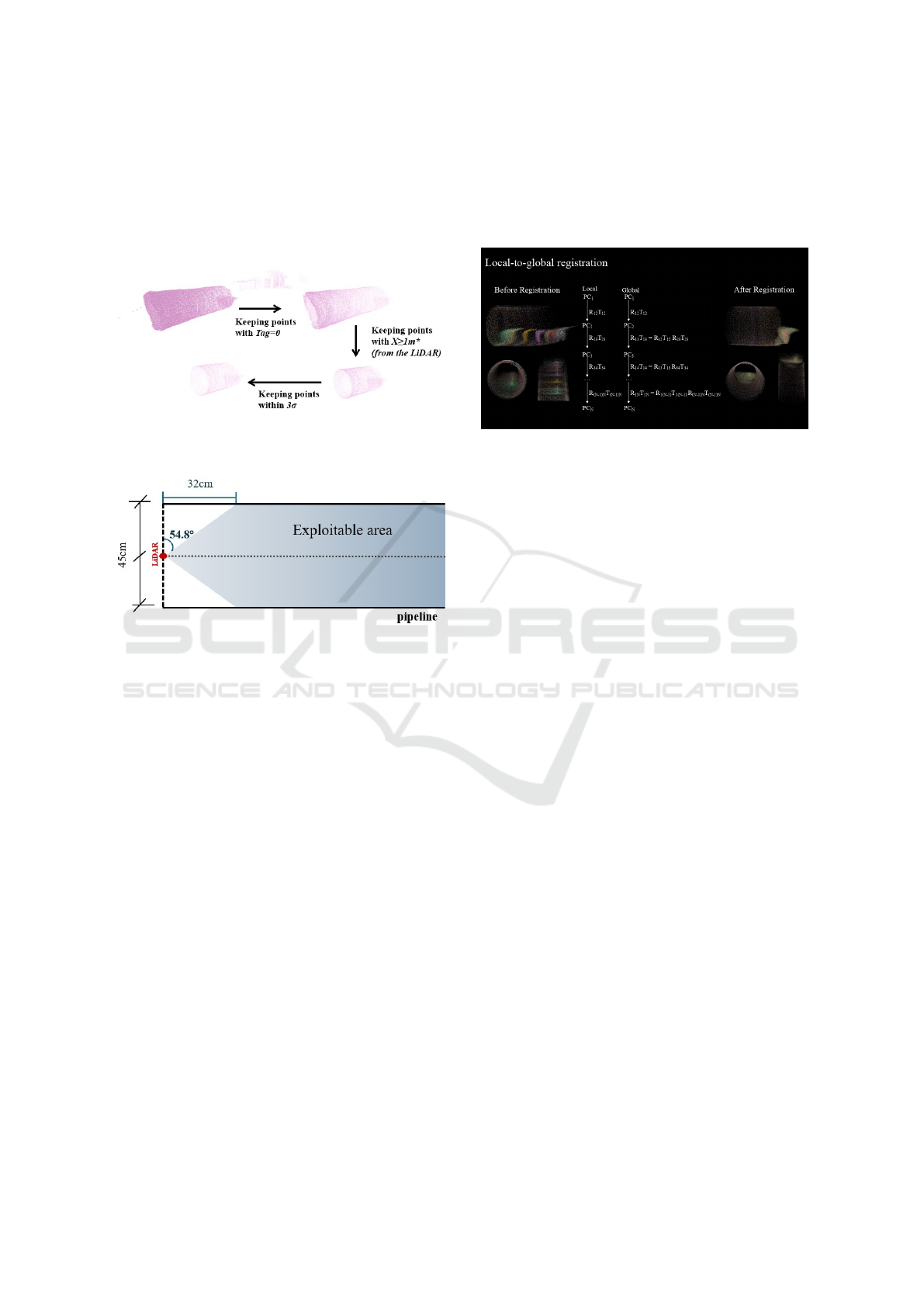
the first measurements are prone to errors and present
high noise levels (2). Therefore, it was decided to re-
ject points closer than a certain distance (1 meter in
the test missions). Finally, to further increase relia-
bility, statistical filtering that removes any remaining
points with noise levels exceeding 3σ is added.
Figure 2: Pre-processing steps are applied to each scan to
remove inaccurate data.
Figure 3: For a 45 cm diameter pipe, LiDAR can scan the
first points of its surface at a distance of 32 cm from its
current position.
2.6 3D Reconstruction via Two-Step
Registration
Due to a pipe’s cylindrical shape, ICP registration of
consecutive point clouds in linear parts of a pipe be-
comes an ill-posed problem, as it is not possible to
accurately estimate all six degrees of freedom (DOF)
without additional constraints. Specifically, transla-
tion along the cylinder’s axis and rotation around this
axis cannot be determined without additional infor-
mation about the robot movement. To address this
issue, external data, such as odometry, is required to
estimate the complete rigid body transformation.
In this work, the individual collected point clouds
are merged using a two-step process based on the It-
erative Closest Point (ICP) registration method, and
data from the robot encoders to perform a 3D re-
construction of the pipeline. Initially, the ICP al-
gorithm aligns two consecutive point clouds in each
iteration by estimating a rigid-body transformation
between them using a point-to-plane ICP approach
(Chen and Medioni, 1992; Rusinkiewicz and Levoy,
2001). These transformations are then expressed in
the coordinate system of the first point cloud to en-
sure the global alignment of all consecutive point
clouds. This step is referred to as local-to-global reg-
istration. After the first local-to-global registration,
Figure 4: Local-to-global registration: the ICP algorithm
aligns two consecutive point clouds in each iteration by es-
timating a rigid-body transformation between them using a
point-to-plane ICP approach algorithm. These transforma-
tions are expressed in the coordinate system of the first point
cloud to ensure the global alignment of all consecutive point
clouds.
the difference between the encoder-provided trans-
formation, which provides the necessary informa-
tion about robot’s movement, and the current ICP-
estimated transformation, is calculated and used as
the new initial transformation for the next local-to-
global registration. A lower threshold is then applied
for the final local-to-global registration, allowing the
algorithm to integrate the absolute motion data from
the encoders and the geometric constraints of the reg-
istered point clouds.
2.7 Pipe Diameter Estimation
The diameter of the 3D reconstruction model is es-
timated by fitting a cylinder surface. A cylinder fit-
ting process is often employed in inspection systems
for multiple tasks such as diameter estimation (Mat-
sui et al., 2010), optimization (Tian et al., 2023), sec-
tioned fitting (Kannala et al., 2008), or establishing a
coordinate frame (Summan et al., 2018). The cylinder
is defined by:
• P
0
=
X
0
Y
0
Z
0
T
: A point on the cylinder’s
central axis,
• P
i
=
X
i
Y
i
Z
i
T
: A point on the surface of the
cylinder, and
• d =
cos(φ)cos(θ) cos(φ) sin(θ) sin(φ)
T
: A
cylinder’s central axis defined by a direction vec-
tor. Here, φ is an elevation angle and θ is an az-
imuthal angle.
GISTAM 2025 - 11th International Conference on Geographical Information Systems Theory, Applications and Management
198
• S
i
: Cylinder’s radius, which is perpendicular from
the surface point P
i
to cylinder’s axis (direction
vector d).
The above parameters form a triangle, where vector
−−→
P
0
P
i
corresponds to the triangle’s hypotenuse. The
adjacent side of the triangle is the projection of
−−→
P
0
P
i
onto the direction vector d, which aligns with the axis
of the cylinder. The opposite side of the triangle cor-
responds to the radius S of the cylinder, which can be
seen as the shortest distance from the point P
i
to the
line through P
0
with direction vector d.
The robot moves along the X-axis. Thus, P
0
can be simplified and assumed to be located at P
0
=
X
0
= 0 Y
0
Z
0
T
. Similarly, since the robot’s mov-
ing axis approximately corresponds to the cylinder’s
axis, the initial values of Y
0
, Z
0
, φ, and θ are set to
zero for simplicity. The radius S
i
is calculated using
the cross-product of
−−→
P
0
P
i
and the direction vector d,
as shown in the equation below:
S
i
=
∥
(P
i
− P
0
) × d
∥
∥
d
∥
(1)
The error e
i
= S
i
− R measures how far a point P
i
de-
viates from the cylinder’s surface, where radius R is
defined as half of the nominal pipe’s diameter.
Levenberg-Marquardt algorithm (Mor
´
e, 1978) is
used to minimize the error function
∑
n
i=1
e
2
i
, where n
are multiple points sampled from the simplified sur-
face of the reconstructed pipeline. The optimization
parameters are:
x =
Y
0
, Z
0
, R, φ, θ
T
(2)
Thus, the optimization problem can be defined as:
min
x
E(x) (3)
Finally, the optimized radius can be converted to
the diameter. Note that a pipe can be modelled as
a perfect cylinder with a consistent diameter along
its length because of its cylindrical shape and the as-
sumption that it is straight. This assumption is crucial,
as it allows the diameter estimation without account-
ing for any variations in curvature that would arise in
a non-straight pipe.
3 RESULTS AND EVALUATION
Before executing an inspection mission, a camera-
LiDAR calibration was performed to assure optimal
results and provide the camera-LiDAR transformation
to the ROS integration tool. A checkerboard selected
for the calibration had seven rows and ten columns;
its cell size was 25 mm. The robot with an integrated
camera and LiDAR sensors was kept fixed while the
checkerboard was moved and rotated for every sub-
sequent image. A total of 25 images were taken for
camera calibration purpose. The camera calibration
process allowed for the estimation of the camera’s in-
terior orientation, which is essential for subsequent
estimation of the relative position and orientation of
the camera with respect to the LiDAR sensor. The
camera intrinsics are given in Table 1 together with
their estimation errors.
Table 1: Camera Intrinsics.
Camera Parameter Computed Value Estimation Error
Focal Length
c
x
(pixel) 370.46 ±0.36
c
x
(pixel) 370.97 ±0.35
Principal Point
x
o
(pixel) 1221.11 ±0.11
y
o
(pixel) 1057.92 ±0.13
Radial Distortion
k
1
0.013138 ±0.000222
k
2
-0.008703 ±0.000117
k
3
0.000747 ±0.000017
Tangential Distortion
p
1
0.000436 ±0.000050
p
2
0.000965 ±0.000050
Mean Reprojection Error
σ
o
(pixel) 0.29
Table 2: Camera-LiDAR Calibration Results.
Rigid transformation Parameters Computed Value
Translation
∆X (cm) 3.53
∆Y (cm) -0.76
∆Z (cm) 5.92
Orientation
ω (deg) -34.76
φ (deg) 87.58
κ (deg) -53.57
Mean Reprojection Error
σ
o
(pixel) 1.48
Next, to estimate a rigid transformation of the
camera system relative to the LiDAR frame, the
camera-LiDAR calibration described in 2.3 was ap-
plied using a simple calibration object consisting
of two crossing retroreflective stripes and an April-
Tag in their intersection. A total of 29 images and
point clouds were captured simultaneously. Table 2
presents the camera-LiDAR calibration results.
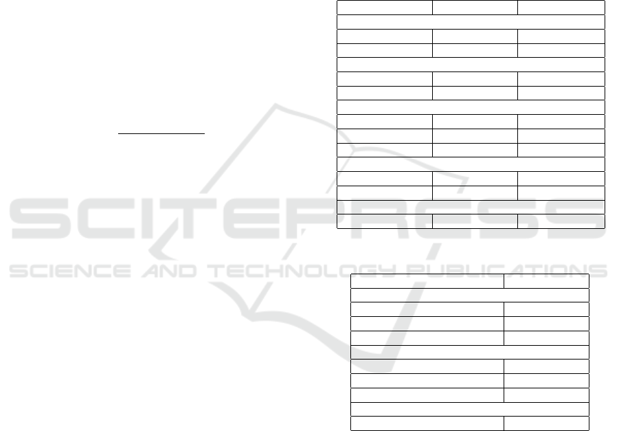
To verify the effectiveness and reliability of the
proposed inspection system, tests were performed in
a controlled laboratory environment. For these tests,
a polished steel pipe with a diameter of 45 cm and
a length of approximately 2.5 meters (Figure 5) was
LiDAR-Based 3D Reconstruction for Robotic Pipelines Inspection
199
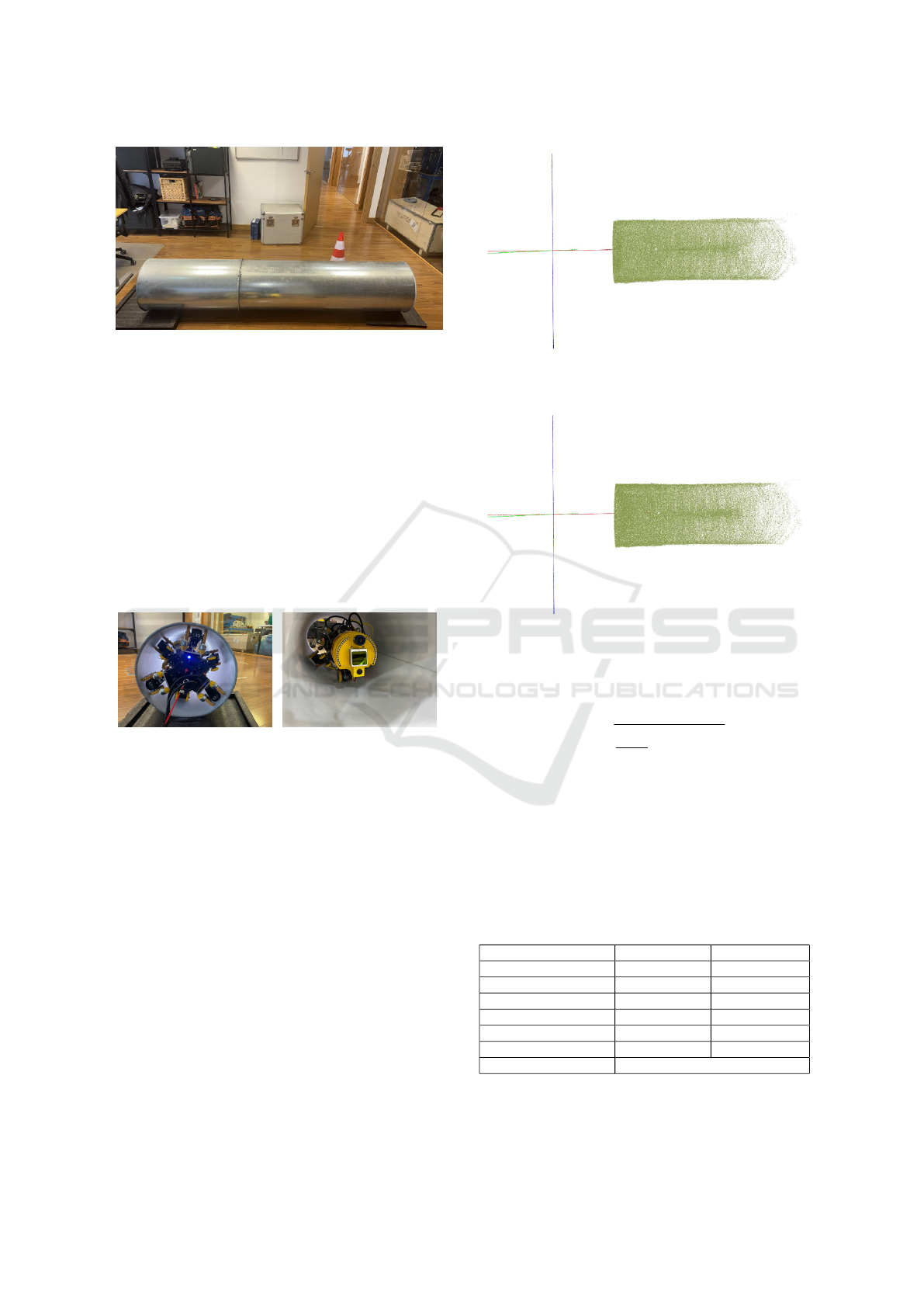
Figure 5: Polished steel pipe.
used.
During the early stages of testing, a challenge with
LiDAR producing noisy data was encountered, as a
result of the highly reflective nature of the polished
surface material. This challenge was addressed by
applying a matte white spray to the pipe’s interior.
This solution effectively minimized reflectivity and
allowed the LiDAR to capture accurate data. It is
important to note that this adjustment was specific to
the reflective properties of polished surfaces, and the
system can perform optimally without surface modi-
fications in less reflective environments such as PVC,
HDPE, clay or plastic pipes.
Figure 6: Robot platform inside the pipe.
To showcase the effectiveness of the proposed
two-step registration method outlined in 2.6, firstly,
3D reconstruction was performed using only the pro-
vided odometry measurements from the robot en-
coders. Due to the noise in the data of the robot’s
IMU sensors, it was determined that an accurate 3D
reconstruction could not be performed without further
optimization, such as the proposed ICP registration.
As detailed in 2.6, the local-to-global registration ef-
fectively addresses this challenge. The comparison
presented in Figure 9 highlights the effectiveness of
the proposed approach.
After completing the two-step registration, the
pipe’s diameter was calculated. Table 3 summarizes
the pipe diameter estimation method results. The es-
timated pipe diameter was 45.431 cm, which closely
matches the nominal pipe diameter of 45 cm.
Root Mean Square Error (RMSE) was calculated
to evaluate the accuracy of the 3D reconstruction
method. It measures the average deviation between
Figure 7: 3D reconstruction model using only odometry
data.
Figure 8: 3D reconstruction model using the proposed two-
step registration method.
the observed 3D points of the 3D reconstruction
model and the approximated cylindrical surface.
σ
o
=
s
1
n − 5
n
∑
i=1
(S
i
− R)
2
(4)
The precision of the estimated pipe’s diameter is
assessed by calculating the confidence interval, ex-
pressed as the two standard deviations of twice the
optimized radius, indicating a 95% confidence level.
Estimation error of all optimized parameters in Table
3 except radius and diameter corresponds to one stan-
dard deviation.
Table 3: Results of the pipe diameter estimation.
Optimization parameters Computed Value Estimation Error
Optimized Yo (m) -0.059 ±0.003
Optimized Zo (m) -0.016 ±0.003
Optimized R (cm) 22.715 ±0.032
Optimized φ (deg) 0.469 ±0.281
Optimized θ (deg) -7.030 ±0.279
Diameter (cm) 45.431 ±0.064 (precision)
σ
o
(cm) 0.48 (RMSE)
GISTAM 2025 - 11th International Conference on Geographical Information Systems Theory, Applications and Management
200

(a) Comparison between the 3D reconstruction
model created using only odometry data (left image,
Figure 7) and the 3D reconstruction model generated
using the proposed method (right image, Figure 8)
(b) Comparison of the registration process using
raw data (top image), using only odometry measure-
ments (middle image, Figure 7), and using the pro-
posed two-step method (bottom image, Figure 8).
Figure 9: Comparison of the registration processes.
4 CONCLUSIONS
This work developed and evaluated a preliminary im-
plementation of a robotic inspection system for non-
reflective pipelines. The robotic system features six-
wheeled arms, which enhance stability and adaptabil-
ity for pipeline diameters ranging from 30 cm to 45
cm. Combining the MID-70 LiDAR and the XIMEA
camera enables wide coverage and high-resolution
data acquisition. Using accurate calibration of LiDAR
and camera sensors, it allows 3D reconstruction via a
two-step registration method. Evaluation results vali-
date the proof-of-concept, demonstrating the system’s
efficiency by achieving a precision higher than 0.5 cm
in diameter estimation and accuracy higher than 2cm
in 3D reconstruction.
This study presents a pilot implementation and is
not without limitations. First, the robot must be re-
designed to inspect pipes with diameters larger than
45cm. Although the camera is integrated and ready
to be used in the robot platform, its usage is not pre-
sented in this initial study. Experiments are conducted
only in a controlled laboratory environment with a
single pipe type, and real-world scenarios with vary-
ing pipe materials, diameters, and environmental con-
ditions should be explored. Finally, this initial case
study lacks a comparison analysis of the proposed
method with other state-of-the-art systems.
Future improvements will focus on leveraging
camera data to integrate color mapping into a 3D
reconstruction method and allow visual inspection
of the pipelines (identifying obstacles, defects, etc.).
Moreover, a robot platform will be redesigned to re-
fine the system for diverse pipeline materials and di-
ameters. Two-step registration and diameter estima-
tion methods will also be refined to handle more chal-
lenging pipes with non-constant diameters. Finally, a
refined robotic system will be benchmarked to iden-
tify its potential limitations, validate its robustness,
and demonstrate its practical usability in real-world
pipeline inspection scenarios.
ACKNOWLEDGEMENTS
This work was part of LASER4TWIN project, sup-
ported by the European Union through the EU-funded
project PIMAP4SUSTAINABILITY ”Photonics for
International Markets and Applications for Sustain-
ability”, in its Innovation Open Call. The authors
would also like to express their gratitude to their part-
ner in the LASER4TWIN project, CIS Robotics, par-
ticularly Christian J. Robledo and Adri
´
an
´
Alvarez
Garc
´
ıa, for designing and manufacturing the robot
and for integrating the developed technologies.
REFERENCES
Ab Rashid, M. Z., Mohd Yakub, M. F., Zaki bin Shaikh
Salim, S. A., Mamat, N., Syed Mohd Putra, S. M.,
and Roslan, S. A. (2020). Modeling of the in-pipe in-
spection robot: A comprehensive review. Ocean En-
gineering, 203:107206.
Baballe, M. A., Bello, M. I., Hussaini, A., and Musa, U. S.
(2022). Pipeline inspection robot monitoring system.
Journal of Advancement in Robotics, 9(2):27–35.
Bouguet, J.-Y. (2023). Camera Calibration Toolbox for
Matlab.
Chen, Y. and Medioni, G. (1992). Object modelling by reg-
istration of multiple range images. Image and Vision
Computing, 10(3):145–155.
Elankavi, R. S., Dinakaran, D., Chetty, R. K., Ramya, M.,
and Samuel, D. H. (2022). A review on wheeled type
in-pipe inspection robot. International Journal of Me-
chanical Engineering and Robotics Research, 11(10).
Grammatikopoulos, L., Papanagnou, A., Venianakis, A.,
Kalisperakis, I., and Stentoumis, C. (2022). An Ef-
LiDAR-Based 3D Reconstruction for Robotic Pipelines Inspection
201

fective Camera-to-Lidar Spatiotemporal Calibration
Based on a Simple Calibration Target.
Gunatilake, A., Piyathilaka, L., Tran, A., Vishwanathan,
V. K., Thiyagarajan, K., and Kodagoda, S. (2021).
Stereo Vision Combined With Laser Profiling for
Mapping of Pipeline Internal Defects. IEEE Sensors
Journal, 21(10):11926–11934.
Hansen, P., Alismail, H., Rander, P., and Browning, B.
(2011). Monocular visual odometry for robot local-
ization in LNG pipes. In 2011 IEEE International
Conference on Robotics and Automation, pages 3111–
3116. IEEE.
Heng, L., Li, B., and Pollefeys, M. (2013). CamOd-
oCal: Automatic intrinsic and extrinsic calibration of
a rig with multiple generic cameras and odometry. In
2013 IEEE/RSJ International Conference on Intelli-
gent Robots and Systems, pages 1793–1800. IEEE.
Kakogawa, A., Komurasaki, Y., and Ma, S. (2019).
Shadow-based operation assistant for a pipeline-
inspection robot using a variance value of the image
histogram. Journal of Robotics and Mechatronics,
31(6):772–780.
Kannala, J. and Brandt, S. S. (2006). A generic camera
model and calibration method for conventional, wide-
angle, and fish-eye lenses. IEEE Transactions on Pat-
tern Analysis and Machine Intelligence, 28(8):1335–
1340.
Kannala, J., Brandt, S. S., and Heikkil
¨
a, J. (2008). Measur-
ing and modelling sewer pipes from video. Machine
Vision and Applications, 19(2):73–83.
Karkoub, M., Bouhali, O., and Sheharyar, A. (2021). Gas
pipeline inspection using autonomous robots with
omni-directional cameras. IEEE Sensors Journal,
21(14):15544–15553.
Kazeminasab, S., Aghashahi, M., and Banks, M. K. (2020).
Development of an inline robot for water quality
monitoring. In 2020 5th International Conference
on Robotics and Automation Engineering (ICRAE),
pages 106–113.
Matsui, K., Yamashita, A., and Kaneko, T. (2010).
3-D shape measurement of pipe by range finder
constructed with omni-directional laser and omni-
directional camera. In 2010 IEEE International Con-
ference on Robotics and Automation, pages 2537–
2542. IEEE.
Moein, E. and Himan, H. J. (2022). Automated Condition
Assessment of Sanitary Sewer Pipes Using LiDAR In-
spection Data, pages 136–144. Proceedings. Ameri-
can Society of Civil Engineers (ASCE).
Mor
´
e, J. J. (1978). The levenberg-marquardt algorithm: Im-
plementation and theory. In Watson, G. A., editor, Nu-
merical Analysis, pages 105–116, Berlin, Heidelberg.
Springer Berlin Heidelberg.
Rusinkiewicz, S. and Levoy, M. (2001). Efficient variants
of the ICP algorithm. In Proceedings Third Interna-
tional Conference on 3-D Digital Imaging and Mod-
eling, pages 145–152. IEEE.
Scaramuzza, D., Martinelli, A., and Siegwart, R. (2006). A
Toolbox for Easily Calibrating Omnidirectional Cam-
eras. In 2006 IEEE/RSJ International Conference
on Intelligent Robots and Systems, pages 5695–5701.
IEEE.
Sepulveda-Valdez, C., Sergiyenko, O., Alaniz-Plata, R.,
N
´
u
˜
nez-L
´
opez, J. A., Tyrsa, V., Flores-Fuentes, W.,
Rodriguez-Qui
˜
nonez, J. C., Mercorelli, P., Kolen-
dovska, M., Kartashov, V., Miranda-Vega, J. E., and
Murrieta-Rico, F. N. (2023). Laser Scanning Point
Cloud Improvement by Implementation of RANSAC
for Pipeline Inspection Application. In IECON 2023-
49th Annual Conference of the IEEE Industrial Elec-
tronics Society, pages 1–6. IEEE.
Sepulveda-Valdez, C., Sergiyenko, O., Tyrsa, V., Mer-
corelli, P., Rodr
´
ıguez-Qui
˜
nonez, J. C., Flores-Fuentes,
W., Zhirabok, A., Alaniz-Plata, R., N
´
u
˜
nez-L
´
opez,
J. A., Andrade-Collazo, H., Miranda-Vega, J. E., and
Murrieta-Rico, F. N. (2024). Mathematical Modeling
for Robot 3D Laser Scanning in Complete Darkness
Environments to Advance Pipeline Inspection.
Summan, R., Jackson, W., Dobie, G., MacLeod, C., Mi-
neo, C., West, G., Offin, D., Bolton, G., Marshall,
S., and Lille, A. (2018). A novel visual pipework
inspection system. AIP Conference Proceedings,
1949(1):220001.
Tian, T., Wang, L., Yan, X., Ruan, F., Aadityaa, G. J.,
Choset, H., and Li, L. (2023). Visual-Inertial-Laser-
Lidar (VILL) SLAM: Real-Time Dense RGB-D Map-
ping for Pipe Environments. In 2023 IEEE/RSJ In-
ternational Conference on Intelligent Robots and Sys-
tems (IROS), pages 1525–1531. IEEE.
Zhao, M., Fang, Z., Ding, N., Li, N., Su, T., and Qian, H.
(2023). Quantitative Detection Technology for Geo-
metric Deformation of Pipelines Based on LiDAR.
Zhao, W., Zhang, L., and Kim, J. (2020). Design and analy-
sis of independently adjustable large in-pipe robot for
long-distance pipeline. Applied Sciences, 10(10).
GISTAM 2025 - 11th International Conference on Geographical Information Systems Theory, Applications and Management
202
