
Development of a Proof-of-Concept Portable Electrostimulation
Device for Lower Limbs Blood Flow Enhancement
Ricardo Pinto
1a
, Ana Almeida
1b
, Inês Rocha
1c
, Diogo Carvalho
2d
, Alexander Oks
3e
,
Miguel Carvalho
4f
, João L. Vilaça
1g
and Vítor Carvalho
1h
1
2Ai, School of Technology, Polytechnic University Cávado and Ave, Barcelos, Portugal
2
Klinikum Landkreis Tuttlingen, Tuttlingen, Germany
3
Riga Technical University, Institute of Architecture and Design, Riga, Latvia
4
2C2T, School of Engineering, University of Minho, Guimaraes, Portugal
Keywords: Electrostimulation, Blood Flow, Portability, Lower Limbs, Well-Being, Wearable Device, Proof of Concept.
Abstract: This paper presents the design and implementation of a proof of concept of a wearable electrostimulation
device aimed at improving blood flow in the lower limbs. The portable system, integrated into wearable
compression socks, delivers electrical pulses for muscular stimulation in specific areas of the leg, using
conductive yarns in their structure, promoting better blood flow. This device addresses the growing sedentary
lifestyle and the resulting health issues like poor circulation, which can lead to severe complications. It
features Bluetooth Low Energy (BLE) communication for real-time session control via a mobile application.
The preliminary results demonstrate effective electrical stimulation, validated through testing, ensuring the
feasibility of the system.
1 INTRODUCTION
In modern society, sedentary lifestyles are
increasingly prevalent, characterized by prolonged
periods spent sitting, often in front of screens or
during commutes. This lack of physical activity leads
to insufficient stimulation of the lower limb muscles,
resulting in impaired blood circulation. Over time,
this condition can escalate to serious complications,
including chronic venous insufficiency, tissue
damage, and, in severe cases, lower limb failure.
Prolonged lack of circulation, if unaddressed, may
necessitate amputation and could even be fatal
(Higgins, et al., 2022). While physical exercise such
as walking or running is critical for maintaining
healthy blood flow, not everyone can engage in
a
https://orcid.org/0000-0002-4116-9377
b
https://orcid.org/0009-0005-6611-2720
c
https://orcid.org/0009-0009-7960-7748
d
https://orcid.org/0000-0002-4618-2474
e
https://orcid.org/0000-0001-6925-1842
f
https://orcid.org/0000-0001-8010-6478
g
https://orcid.org/0000-0001-6925-1842
h
https://orcid.org/0000-0003-4658-5844
regular activity due to professional, medical, or
personal constraints. Consequently, alternative
solutions, including pharmacological interventions
and devices designed to stimulate leg muscles and
enhance blood flow, have gained prominence as
viable approaches to mitigating these risks.
(Ashutosh , Dhaniwala, Dudhekar, Goyal, & Patel,
2023)
Currently, portable stimulation devices are
predominantly designed for the abdominal region,
offering limited applicability to other parts of the
body. For the lower limbs, existing equipment tends
to be large and cumbersome, requiring patients to
remain stationary, often lying on a stretcher, to
receive treatment. This lack of portability and
Pinto, R., Almeida, A., Rocha, I., Carvalho, D., Oks, A., Carvalho, M., Vilaça, J. L. and Carvalho, V.
Development of a Proof-of-Concept Portable Electrostimulation Device for Lower Limbs Blood Flow Enhancement.
DOI: 10.5220/0013396700003911
Paper published under CC license (CC BY-NC-ND 4.0)
In Proceedings of the 18th International Joint Conference on Biomedical Engineering Systems and Technologies (BIOSTEC 2025) - Volume 2: HEALTHINF, pages 1007-1017
ISBN: 978-989-758-731-3; ISSN: 2184-4305
Proceedings Copyright © 2025 by SCITEPRESS – Science and Technology Publications, Lda.
1007

practicality restricts their usability in daily life or
during routine activities.
In contrast, compression socks are widely used in
sports such as running and walking to improve blood
flow through passive pressure applied by the tightness
of the textile structure. However, these socks provide
only static compression and lack the capability to
actively stimulate lower limb muscles, which is
essential for enhancing venous return and addressing
more severe circulatory deficiencies.
This gap highlights the need for a portable, user-
friendly solution that combines the benefits of
compression socks with active muscle stimulation.
Such a device could be seamlessly integrated into
compression socks to provide dynamic, localized
stimulation, offering a more effective approach to
improving blood flow in the lower limbs. This
innovative approach would be particularly beneficial
for individuals with sedentary lifestyles, athletes
seeking enhanced recovery, and patients undergoing
rehabilitation.
In response to this need, a wearable device was
developed as a proof of concept to improve blood
flow in the lower limbs through targeted and
responsible use. This innovative device delivers
electrical pulses to stimulate specific muscle groups
in the lower legs, enhancing circulation and
promoting venous return.
The wearable system is designed to be compact
and portable, seamlessly integrating with
compression socks that conduct the electrical
stimulation to precise anatomical points. By
combining the passive benefits of traditional
compression with active muscle stimulation, this
device addresses the limitations of existing solutions.
A key feature of the device is its integration of
Bluetooth Low Energy (BLE) communication,
enabling remote control and customization through a
dedicated mobile application. This functionality
allows users to tailor treatment sessions, including
adjusting stimulation intensity and duration, to meet
individual therapeutic or preventative needs.
This paper is organized into five sections. Section
2 provides an overview of the concept of
electrostimulation, its application as a therapeutic
approach for humans, and the associated benefits.
Additionally, existing market solutions are reviewed
to identify gaps and opportunities for improvement in
addressing lower limb blood flow issues. Section 3
introduces the proposed solution, detailing its
development across three core components: hardware,
firmware, and software. This section outlines the
design process, technical specifications, and
integration of these elements to create a functional
and effective wearable device. Section 4 focuses on
validation tests and results. This includes an
evaluation of the device’s performance, a
demonstration of its usability, and a presentation of
the final product, which comprises a compression
sock enhanced with silver-plated textile yarn and the
wearable device with Bluetooth connectivity. Finally,
Section 5 summarizes the challenges, limitations, and
lessons learned throughout the development process.
Potential areas for improvement are discussed, along
with suggestions for future iterations to enhance the
device’s functionality and usability in subsequent
versions of the project.
2 STATE OF ART
Electrostimulation devices are widely available today,
with each system employing its own unique
mechanisms of operation. Muscle electrostimulation
involves the application of an electric current—
typically low or medium frequency—through
electrodes positioned on the skin. This technique can
induce muscle contractions, facilitating functional
movements or enhancing muscle strength to improve
physical performance.
Electrostimulation systems have found extensive
application in both physiotherapy and sports. They
are commonly used for the prevention, treatment, and
management of various disorders affecting the
neuromuscular system. When applied appropriately,
these systems represent a safe and effective method
for promoting neuromuscular function and improving
overall physical health (Sausport, 2024).
2.1 Electrostimulation
The use of electrostimulation dates to ancient times
when electric eels were employed to alleviate pain in
limbs. Over the centuries, advances in understanding
the effects of different waveforms on muscle and
nerve function have allowed for the safe and effective
application of electrostimulation to optimize patient
outcomes in alignment with specific care plans. A
fundamental understanding of the properties of
electricity and current flow is essential for the safe use
of electrostimulation on the human body.
Current flow is governed by its direct
proportionality to voltage and inverse proportionality
to resistance. Biological tissues exhibit varying
electrical properties: the skin, like nerve and muscle
membranes, possesses capacitance, enabling it to
store electrical charges and resist changes in current
flow. Meanwhile, skin and fatty tissues act as
WHC 2025 - Special Session on Wearable HealthCare
1008
resistors, opposing current flow. The current naturally
follows the path of least resistance within the body,
driven by ionic flow—positive and negative charges
attract, while like charges repel (Stillings D., 1975),
(Heidland, et al., 2013).
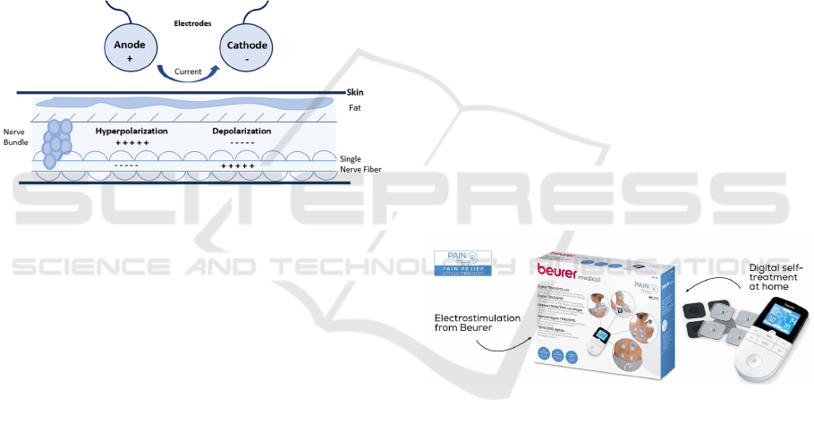
Figure 1 illustrates the working principle of
electrostimulation. The anode and cathode serve as
points of contact with the skin and carry opposite
charges. At the anode, negative ions migrate toward
the positive pole, resulting in increased acidity,
protein coagulation, and tissue hardening. Conversely,
at the cathode, positive ions migrate toward the
negative pole, causing increased alkalinity, protein
liquefaction, and tissue softening. These processes
contribute to improved circulation as the body strives
to restore homeostasis and maintain a neutral pH level
(College, 2024).
Figure 1: Principle of operation of electrostimulation.
Today, numerous commercial electrostimulation
solutions are available, each offering various control
modes and therapy session options. However, all
these systems are fundamentally based on two core
electrostimulation concepts (Digital, 2024):
• Muscle Electrostimulation (EMS) involves
the application of low-voltage stimuli,
typically with currents ranging from 80 to
100 mA and frequencies between 10 and 100
Hz. EMS primarily targets the motor nerve
fibres of muscles to induce muscle
contractions. This method is commonly used
for muscle strengthening and rehabilitation.
• Transcutaneous Electrical Nerve Stimulation
(TENS) is primarily employed for pain
management by blocking pain signals.
Unlike EMS, TENS uses electrodes placed
on sensitive nerve points rather than motor
nerve fibres. This stimulates the production
of endorphins and provides small electrical
impulses that activate pain-modulating
mechanisms in the body.
In summary, both EMS and TENS deliver
electrical impulses through electrodes placed on the
skin near the target area, but they serve distinct
purposes: TENS aims to alleviate pain, while EMS is
used to relax, strengthen, and improve muscle
function. The repetitive muscle contractions induced
by EMS promote enhanced blood circulation, prevent
muscle atrophy, stimulate muscle growth, aid in
muscle relaxation, and reduce inflammation.
Given the objective of this project—to develop a
device that enhances blood circulation—a Muscle
Electrostimulation (EMS) device was identified as
the most suitable choice due to its direct impact on
improving blood flow through muscle activation.
2.2 Current Solutions and
Standardization
By analysing several commercial models, we
identified several common characteristics, including:
• Wireless operation, powered by compact,
portable batteries.
• Simple electrodes and pads designed for skin
contact.
• Technical specifications, including voltage,
current, and frequency parameters.
In the context of available commercial solutions,
many devices exhibit similarities to the EM49 model
(Beurer, 2023), as shown in Figure 2. This model
exemplifies the standard design and functionality
commonly seen in the market.
Figure 2: Equipment EM49 (Beurer, 2023).
This equipment is manufactured by Beurer and
operates with a maximum voltage of 100Vpp and a
current of up to 200mA. Additionally, OMRON
produces devices such as the HeatTens (HV-F311-E)
(OMRON, 2023), which operates at 70V and can
generate 100µs pulses.
A significant portion of the scientific literature
focuses on the development of human-machine
interfaces, where users can control the activation and
deactivation of electrostimulation signals. However,
the electrostimulation signals themselves are
typically generated and managed by compact
commercial devices, such as power supplies, which
often lack advanced electrical consumption
management (De Almeida, Bertucci Borges, & de
Development of a Proof-of-Concept Portable Electrostimulation Device for Lower Limbs Blood Flow Enhancement
1009
Azevedo Dantas, 2022), (Özgüner, Alaca, Başkurt, &
Akman, 2021). Furthermore, some studies fail to
consider dynamic and user-centred interactions, as
many systems use static signals that cannot be
modified. In many cases, these solutions are
presented as mere proof-of-concept projects rather
than fully developed, functional systems (Velloso,
2005).
3 DEVELOPED WEARABLE
DEVICE
The developed solution consists of three main
components:
• Firmware: This component manages the
control of the electrostimulation waveform,
as well as the reception, processing, and
transmission of messages between the
system and the smartphone.
• Hardware: This encompasses all the
electrical circuits necessary for the system's
operation, including power supply, control
circuits, and actuation mechanisms.
• Software: A mobile application that enables
the creation, editing, and monitoring of
electrostimulation sessions.
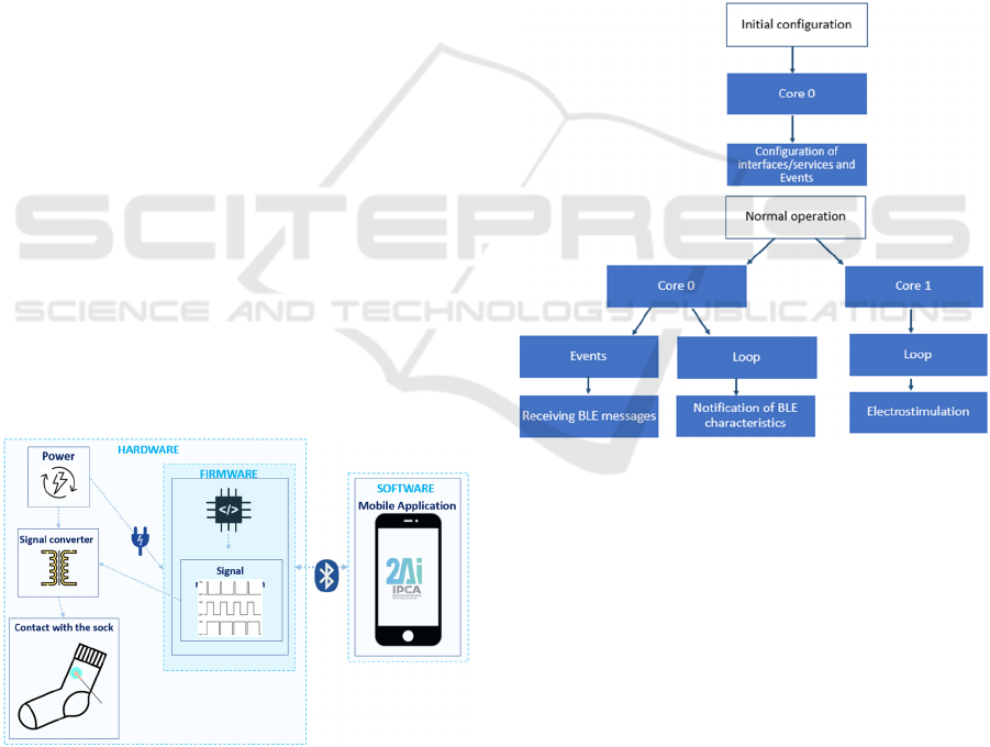
Figure 3 illustrates the system architecture,
highlighting the key modules, including the
embedded system responsible for controlling the
electrostimulation of the socks through I/O signals.
The embedded system also facilitates Bluetooth
communication with the mobile application, enabling
seamless interaction and control.
Figure 3: Electrostimulation system architecture.
3.1 Firmware
The ESP32 (Espressif, 2023) was selected as the
microcontroller for the system due to its integrated
Bluetooth Low Energy (BLE) communication
capabilities and dual-core architecture, which allows
for the simultaneous execution of two tasks. The roles
of the two cores are as follows:
• Core 0: Responsible for the initial
configuration of interfaces, services, and
events. Once configured, it handles the
reception of messages and manages
notifications related to BLE characteristics.
• Core 1: Dedicated to processing and
executing the control of the
electrostimulation signal, ensuring proper
modulation and operation of the stimulation.
Figure 4 illustrates the operational workflow of
the electrostimulation module, focusing on the
firmware development and task management across
the two cores.
Figure 4: Configuration and operation of the electro-
stimulation module.
3.2 Hardware
The hardware module developed includes several
blocks, including battery management and signal
modelling.
3.2.1 Battery Management
One of the requirements of the system was to use an
internal lithium battery that could be charged via 5V,
the most common nowadays. The MCP73831-2-OT
(Farnell, 2023), was used to control battery charging
via USB. This is a low-cost and widely used
controller. Figure 5 illustrates the battery charging
circuit designed for the solution.
WHC 2025 - Special Session on Wearable HealthCare
1010
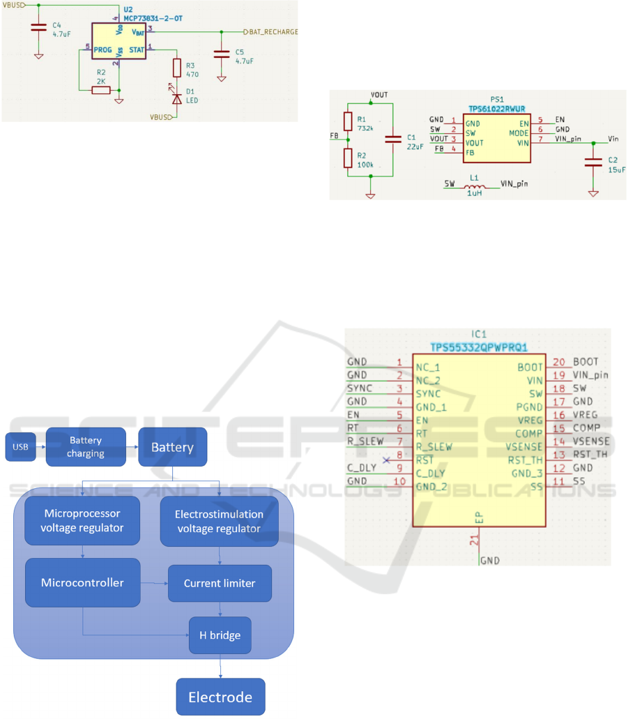
Figure 5: Lithium battery charging circuit.
3.2.2 Electrostimulation Signal Modeling
To model the electrical signal needed to stimulate the
muscle, the following steps are required:
Raising the electrical voltage: The module's
battery was 3.7V, and it was needed to raise the
voltage (45V in this case).
Limit current: Control the maximum current to
prevent damage to the user during
electrostimulation, such as electrical
discharges.
Reverse current direction: To have a two-phase
signal, it was needed to change the current
direction.
In Figure 6, one can graphically see the various
blocks for modeling the electrical signal.
Figure 6: Electrical signal modeling.
Initially, to raise the voltage, were integrated two
booster circuits connected in series. An initial one that
powers up 3.7V to 5V and a second one that powers
up 5V to a maximum of 60V.
The TPS61022RWUR (Instruments, TPS61022 |
Buy TI Parts | TI.com, 2024) was used for the first
regulator, whose main function was to guarantee a
fixed 5V for the next regulator, even if the voltage
supplied by the battery decreases. It also has the
possibility of ON/OFF control, using the Enable pin.
The circuit developed for the first booster is
shown in Figure 7.
Figure 7: Circuit with the TPS61022RWUR.
Connected in series to the TPS61022RWUR is the
TPS55332QPWPRQ1 (Instruments, TPS55332-Q1 |
Buy TI Parts | TI.com, 2024). This booster can adjust
the output voltage up to 60V. Figure 8 shows the
module in the schematic developed.
Figure 8: Circuit with TPS55332QPWPRQ1.
The output voltage is set using the ratio of
resistors between the VREG and VSense pins,
according to the formula on the datasheet
(Instruments, TPS55332-Q1 | Buy TI Parts | TI.com,
2024). However, a potentiometer that has a range of
values within the desired range has been placed, so
fine-tuning is done a posteriori, and with the stability
of the system, the value of the precision resistor to be
placed to replace the potentiometer will be defined.
The voltage configuration circuit used in this project
is shown in Figure 9.
Development of a Proof-of-Concept Portable Electrostimulation Device for Lower Limbs Blood Flow Enhancement
1011
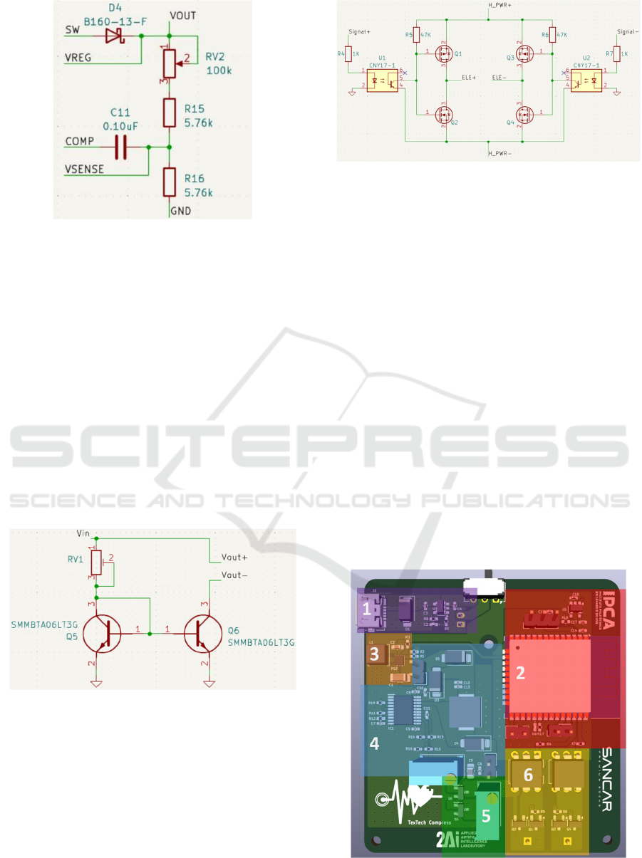
Figure 9: TPS55332QPWPRQ1 output voltage configura-
tion circuit.
In this way, it was possible to obtain a final output
voltage of 45V. Having that assured, it was necessary
to limit the current. It was used a current mirror
circuit, in which two BJT (Bipolar Junction
Transistor) transistors and a resistor guarantee a fixed
and stable current at the output.
Simulation software was used to help with the
development, and it was concluded that a resistance
of 2kΩ is needed to guarantee 20mA at 40V.
A potentiometer operating in the desired range of
values was placed in the module to be adjusted
according to the simulation and guarantee the output
current. The transistors selection was according with
the desired voltages and currents, resulting in the
circuit shown in Figure 10.
Figure 10: Portable module current mirror circuit.
With the voltage and current stabilized, it was
necessary to create a circuit capable of creating a two-
phase pulse. To do this, an H-bridge circuit was
developed. This circuit used mosfets controlled by
signals from the microcontroller. These control
signals were isolated using optocouplers to avoid
damaging the ESP32. All the components were
chosen according to the voltages and currents
circulating in this part of the circuit. The H-bridge
developed is shown in Figure 11.
Figure 11: H Bridge circuit developed.
3.2.3 PCB Layout and Properties
As far as the layout is concerned, all the rules required
by the component datasheets were considered, and
the result is shown in Figure 12.
Note that the components are only in the upper
part, with the lower part only containing the battery
connector.
Looking at Figure 12 one can see:
Purple (1): USB type-C connector, charging
circuit and selector switch for disconnecting
the battery from the charger or from the circuit.
Red (2): ESP32 with regulator and surrounding
circuitry (enable pin, boot pin, etc.).
Orange (3): 3.7V battery to 5V converter.
Blue (4): Converter from 5V to 45V, with
potentiometer for adjusting the output voltage.
Green (5): Current limiting circuit, with
potentiometer for adjusting the maximum
current.
Yellow (6): H-bridge circuit with output for the
electrodes.
Figure 12: PCB layout by blocks.
WHC 2025 - Special Session on Wearable HealthCare
1012
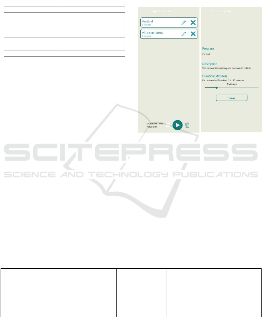
Table 1 presents the final specifications of the
module.
Table 1: Specifications of the developed module.
Specification Value
Charging voltage 5V
Out
p
ut volta
g
e 45V
Batter
y
volta
g
e 3.7V
Maximum output
current
20mA
O
p
eratin
g
fre
q
uenc
y
1
–
100 Hz
Pulse width 50 uS
–
100 uS
Si
g
nal t
yp
e Two-
p
hase s
q
uare wave
3.3 Software
As previously referred the mobile application was
developed to act as a remote control for the
electrostimulation system. It includes the following
characteristics:
Connecting to a Bluetooth Low Energy device.
Creation of a new electrostimulation session.
Add electrostimulation programmes to the
session.
Edit electrostimulation session programs.
Start and pause the electrostimulation session.
As referred, BLE was used for communication
between the stimulation module and the Smartphone
(Bluetooth Special Interest Group, 2023), which is the
most widely used communication in wearable health
devices. In this work, a service was created with four
characteristics:
IsRunning – Indicates if a treatment session is
in progress.
RemainingTime – Indicates the time remaining
until the end of the treatment session in
seconds.
SendProgram – Characteristic where the
treatment session is sent from the Smartphone
to the electrostimulation module.
StopProgram – Sending a message to stop the
session.
The mobile application was developed in .NET
MAUI (Microsoft, 2024). Figure 13 shows the
‘treatment session’ pages, which contains the session
created by the user and then sent to the module
(Figure 13 left).
Figure 13: Left: Treatment edition page. Right: Treatment
session page.
In Figure 13 right one can see the page for
selecting the programme to add to the treatment
session, as well as the duration of the session. It also
integrates brief information about the purpose of the
programme to be added.
The application currently has six programs to be
added to the treatment session, as shown in Table 2.
What differs between the programs is the frequency,
pulse length and activation and pause times.
By selecting the program for the
electrostimulation session, the user also sets the
duration.
As the programs are stored in the application, new
programs can be added in the future without having
to change the module's firmware.
Table 2: Electrostimulation programs available on the mobile application.
Program Frequency (Hz) Pulse length(µsecs) Activation time(sec) Pause time(sec)
Train
90 60 1 1
K
nead
10 100 2 2
M
assa
g
e Low
F
requenc
y
10 100 2 1
M
assa
g
e
H
i
g
h
F
requenc
y
100 50 4 4
A
ctivation Lo
w
F
requenc
y
30 100 2 2
A
ctivation
H
i
g
h
F
requenc
y
90 60 2 2
Development of a Proof-of-Concept Portable Electrostimulation Device for Lower Limbs Blood Flow Enhancement
1013
4 DEVICE FUNCTIONING
RESULTS
Once the layout had been concluded, the assembly
and respective tests were carried out.
During the tests, the two-phase electrical signal
was validated, as well as the current limitation, since
when the skin was short-circuited, the voltage
remained stable. Sensitivity was also validated on the
skin with gel pads specific for electrostimulation
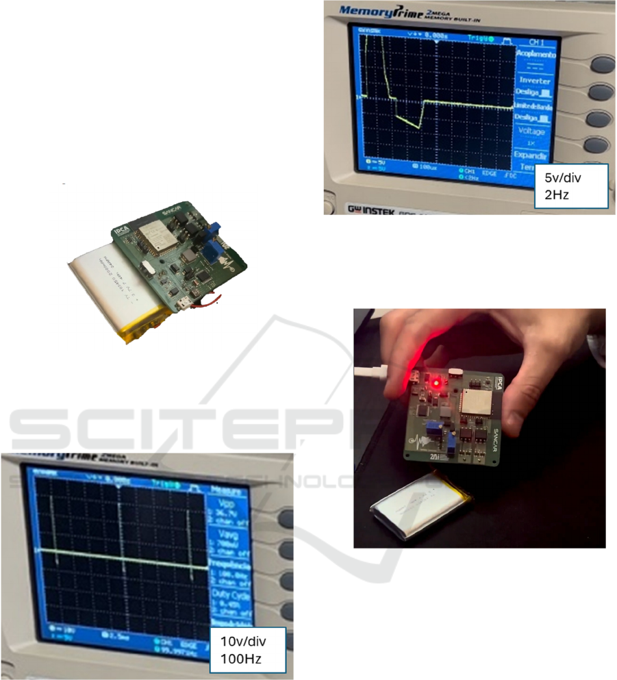
devices. Figure 14 shows the assembled PCB.
Figure 14: Assembled portable PCB.
In Figure 15 one can see the result of a test
involving biphasic pulses at a frequency of 100Hz,
without the pad being in contact with human skin.
Figure 15: Biphasic pulse at 100Hz.
In Figure 16 one can see the result of another test
at a frequency of 2Hz, now with skin contact, where
a small amount of expected distortion can be
observed.
Figure 16: Biphasic pulse at 2 Hz.
In Figure 17, we can see the device being charged
via USB-C, with the LED signalling charging in
progress.
Figure 17: Charging the device.
In Figure 18 left, one can see an example of an
electrostimulation session in progress and the
application indicating the time remaining. In Figure
18 right, one can see the module running the
electrostimulation session, with the pad in contact
with the skin.
WHC 2025 - Special Session on Wearable HealthCare
1014
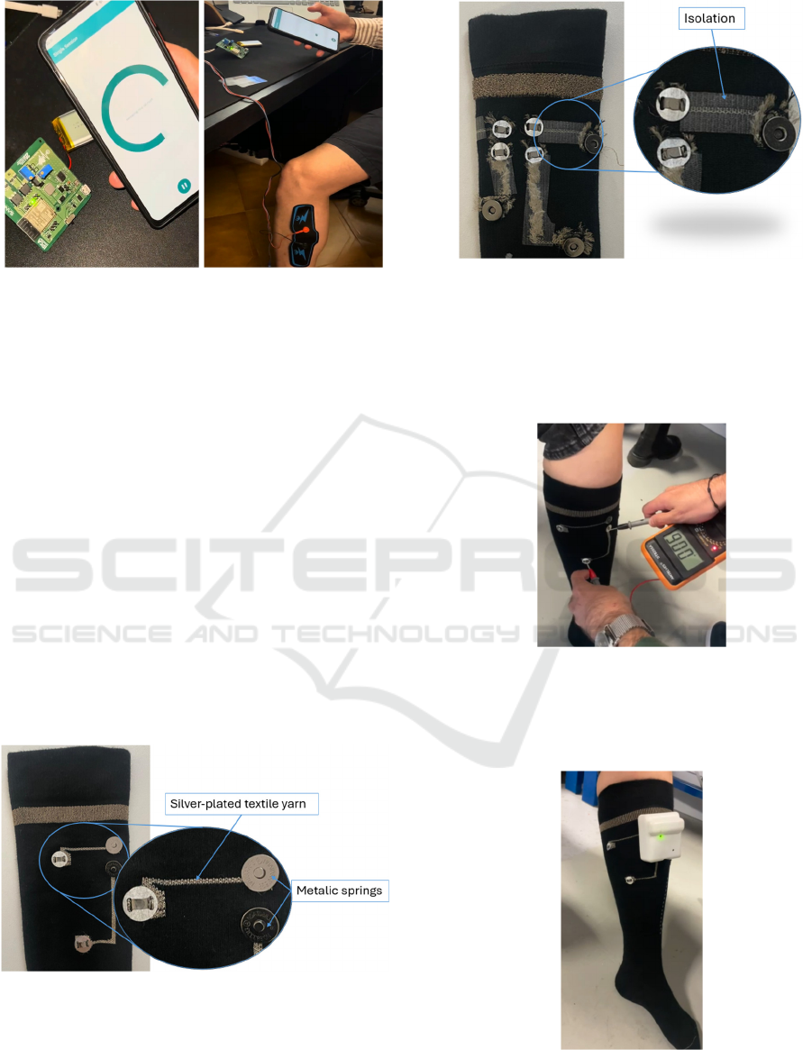
Figure 18: Left: Electrostimulation session in progress.
Right: Module in operation.
After validating the electronics, we moved on to
the development of the casing and its integration in
the designed compression socks.
The following considerations were considered
when developing the casing and compression socks:
• The module must be easily removable so
that the socks can be washed.
• The electrical pulse from the device to each
muscle must be conducted using textile
conductive threads.
For this reason, a prototype of the compression
sock was built, in which the electrical pulse is
conducted through a silver-plated yarn. Magnetic
snaps were placed at the contact points to attach the
module to the socks, as well as the medical pads for
electro-stimulation.
Figure 19 shows the outer part, with the magnetic
snaps that will allow contact with the module and the
pads, as well as the silver-plated conductive yarns.
Figure 19: Outside of the compression socks.
Figure 20 shows the inside of the socks, which has
been insulated to prevent the conductive yarn from
coming into contact with the skin, making it possible
only at the specific points of the muscle, where the
medical pad is inserted.
Figure 20: Inside of the compression socks.
Tests were carried out to validate the electrical
conduction of the textile, as well as the sensitivity of
the pulse on human skin.
Figure 21 shows confirmation of the textile's
conduction.
Figure 21: Electrical conductivity tests on textile.
Figure 22 shows the sensitivity tests on human
skin, thus validating the functioning of the developed
product.
Figure 22: Final working prototype in a human.
Development of a Proof-of-Concept Portable Electrostimulation Device for Lower Limbs Blood Flow Enhancement
1015
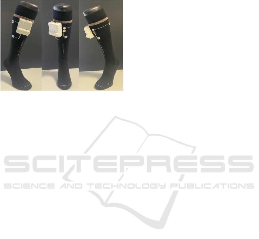
This resulted in the final prototype shown in
Figure 23.
Figure 23: Final prototype
5 CONCLUSION AND FUTURE
WORK
In conclusion, all the objectives of this research have
been successfully achieved. A proof of concept has
been developed for a wireless electrostimulation
device, controlled via a smartphone application. This
device can be connected to socks with specific
characteristics that conduct electric current to
targeted areas of the lower legs, thereby enhancing
blood flow through muscle activation.
During the development process, several
challenges were encountered, such as the issue of
accurately sensing the electrical pulse. This led to an
in-depth investigation into the problem, ultimately
resulting in a clear understanding and an effective
solution.
The Bluetooth Low Energy (BLE)
communication between the smartphone and the
module, as well as the electrical signal delivery to the
electrodes, have been thoroughly validated and
confirmed to be operational. The mobile application
has been successfully compiled and tested on various
Android devices, ensuring compatibility across
different Android versions. Although testing in an
iOS environment was not conducted, it is feasible to
compile the application on iOS using a development
account and an Apple device, without needing to
modify the core code.
In terms of electrical improvements, we identified
the potential for enhancing pulse modulation, which
is currently generated exclusively by hardware, and
current control, which is managed using digital
potentiometers.
From a firmware perspective, further
improvements could be made in battery management,
such as implementing a sleep mode for the ESP32
when no treatment session is in progress, to optimize
power consumption.
Finally, the software component of the system
offers several opportunities for enhancement. The
current mobile application is functional, but its user
interface could be further refined for better aesthetic
appeal and user experience. The application was
initially developed to demonstrate the system's
functionality and control mechanisms, leaving room
for design improvements. Compared to other
equipment on the market, this meets the technical
specifications for EMS equipment and is a good basis
for a commercial version.
Taking advantage of the interactivity between the
device and the smartphone, a potential extension of
this solution, we propose the development of an
online treatment platform that would allow healthcare
professionals, such as doctors and physiotherapists, to
remotely monitor and manage users' treatment
sessions.
ACKNOWLEDGEMENTS
The authors are grateful to FCT for funding under the
programs UIDB/05549/2020, UIDP/05549/2020 and
UID/CTM/00264/2020 and to the company
SANCAR – SANCAR PREMIUM SOCKS, LDA
under the project “TexTechCompress” POCI-02-
0853-FEDER-179821. This work was also funded by
the Innovation Pact HfFP–Health From Portugal, co-
funded from the” Mobilizing Agendas for Business
Innovation” of the ”Next Generation EU” program of
Component 5 of the Recovery and Resilience Plan
(RRP), concerning ”Capitalization and Business
Innovation”, under the Regulation of the Incentive
System ”Agendas for Business Innovation”.
REFERENCES
Ashutosh , L., Dhaniwala, N., Dudhekar, U., Goyal, S., &
Patel, S. (2023). A Comprehensive Review of
Treatment Strategies for Early Avascular Necrosis.
Cureus, e50510.
Beurer. (10 de June de 2023). EM 49 - Digital TENS/EMS
unit. Obtido de beurer:
https://www.beurer.com/web/gb/products/medical/pai
n-therapy-tens/em-49.php
Bluetooth Special Interest Group. (10 de June de 2023).
Bluetooth® Wireless Technology. Obtido de bluetooth:
WHC 2025 - Special Session on Wearable HealthCare
1016

https://www.bluetooth.com/learn-about-
bluetooth/tech-overview/
College, L. C. (20 de January de 2024). Foundations of
Electrical Stimulation - PTA 101 Introduction to
Clinical Practice. Obtido de Lane Community College:
https://media.lanecc.edu/users/thorpeb/pta101lab/Foun
dationsofEstim/FoundationsofEstim_print.html
De Almeida, T. F., Bertucci Borges, L. H., & de Azevedo
Dantas, A. F. (2022). Development of an IoT
Electrostimulator with Closed-Loop Control. Sensors,
22-29.
Digital, H. (28 de April de 2024). O que é eletroestimulação
fisioterapia e para que serve? Obtido de clinicavicci:
https://www.clinicavicci.com.br/o-que-e-
eletroestimulacao-fisioterapia-e-como-funciona/
Espressif. (10 de June de 2023). ESP32-DevKitC Board.
Obtido de ESP32-DevKitC:
https://www.espressif.com/en/products/devkits/esp32-
devkitc
Farnell. (12 de June de 2023). MCP73831T-2ACI/OT -
Microchip - Battery Charger for 1 Cell of Li-Ion, Li-Pol
battery, 6V input. Obtido de Farnell:
https://pt.farnell.com/microchip/mcp73831t-2aci-ot/li-
ion-li-poly-charge-
controller/dp/1332158?CMP=KNC-GPT-GEN-KWL-
High-Quality-Control-8-16-
22&mckv=_dc|pcrid|580775045009|&gad=1&gclid=C
jwKCAjwhJukBhBPEiwAniIcNb8ipZIlUpSy-
bbjq7Qjjb9SK2Syh12pW9snT2MAoi9EFI
Heidland, A., Fazeli, G., Klassen, A., Sebekova, K.,
Hennemann, H., Bahner, U., & Di Iorio, B. (2013).
Neuromuscular electrostimulation techniques:
historical aspects and current possibilities in treatment
of pain and muscle waisting. Clinical nephrology, 79
Suppl 1, S12–S23.
Higgins, S., Pomeroy, A., Bates, L., Paterson, C., Barone
Gibbs, B., Pontzer, H., & Stoner, L. (2022). Sedentary
behavior and cardiovascular disease risk: An
evolutionary perspective. Frontiers in Physiology,
962791. Obtido em 23 de janeiro de 2021, de
ford.pt/experiencia-ford/historia-e-herenca-marca-ford
Instruments, T. (11 de September de 2024). TPS55332-Q1
| Buy TI Parts | TI.com. Obtido de TI Parts:
https://www.ti.com/product/TPS55332-Q1/part-
details/TPS55332QPWPRQ1
Instruments, T. (11 de September de 2024). TPS61022 | Buy
TI Parts | TI.com. Obtido de TI Parts:
https://www.ti.com/product/TPS61022/part-
details/TPS61022RWUR
Microsoft. (8 de March de 2024). .NET Multi-platform App
UI. Obtido de dotnet.microsoft:
https://dotnet.microsoft.com/en-us/apps/maui
OMRON. (10 de June de 2023). HeatTens HV-F311-E.
Obtido de mron-healthcare: https://www.omron-
healthcare.com/products/heattens
Özgüner, Ş., Alaca, Ö., Başkurt, F., & Akman, H. (2021).
Low Cost Functional Electrostimulation. Research
Journal of Biomedical and Biotechnology, 38-43.
Sausport. (3 de May de 2024). Eletroestimulação - O que é
e as suas diferentes aplicações. Obtido de Sausport:
https://sausport.com/eletroestimulacao-o-que-e-e-as-
suas-diferentes-aplicacoes/
Stillings D. (1975). A survey of the history of electrical
stimulation for pain to 1900. Med Instrum, 255-9.
Velloso, J. (2005). Estimulador elétrico muscular
programável. Rio de Janeiro: Universidade Federal do
Rio de Janeiro - Escola de Engenharia.
Development of a Proof-of-Concept Portable Electrostimulation Device for Lower Limbs Blood Flow Enhancement
1017
