
An Adaptive Neuro-Fuzzy Inference Approach of AOA/AOS Data Fusion
for Small Fixed-Wing UAV
Bowen Duan
1,† a
, Yiming Wang
1,† b
, Heng Wang
1,† c
, Yunxiao Liu
1,† d
, Han Li
2,† e
and
Jianliang Ai
1,
*
f
1
Department of Aeronautics & Astronautics, Fudan University, 220 Handan Road, Shanghai 200433, China
2
Department of Electrical Engineering, University of Shanghai for Science and Technology, 516 Jungong Road, Shanghai
200093, China
Keywords:
Angle of Attack, Angle of Sideslip, Small-Sized UAV, Data Fusion, Adaptive Network-Based Fuzzy Inference
System.
Abstract:
Accurate measurement of angle of attack (AOA) and angle of sideslip (AOS) is crucial for ensuring the safe
operation of fixed-wing unmanned aerial vehicles (UAVs) and conducting reliable flight performance evalua-
tions. Given the limited payload capacity of small-sized UAVs, lightweight wind vane probes are commonly
employed. Although installing wind vane sensors at the nose typically yields accurate measurements, this
placement is impractical for UAVs with front-mounted propellers. An alternative is to position the sensors
beneath the wing, but this configuration introduces measurement inaccuracies due to propeller-induced slip-
stream and fuselage obstruction. To address these challenges, estimating AOA and AOS using inertial data
through the unscented Kalman filter (UKF) offers a more robust solution, as it is less affected by external dis-
turbances. This study introduces an adaptive network-based fuzzy inference system (ANFIS) for AOA/AOS
data fusion, which compensates for inaccuracies in sensor measurements by integrating UKF-estimated AOA
and AOS values. Flight test results demonstrate that the proposed ANFIS model achieves an average relative
error of less than 15 %, with the average relative errors being 10.26 % for AOA and 12.77 % for AOS. This
fusion approach significantly enhances the accuracy of AOA and AOS measurements, providing a valuable
reference for small-sized fixed-wing UAVs.
1 INTRODUCTION
The angle of attack (AOA) and angle of slip (AOS)
are important parameters affecting fixed-wing un-
manned aerial vehicles (UAVs) aerodynamics. There-
fore, accurate measurement of AOA and AOS is nec-
essary for ensuring the safe flight of fixed-wing UAVs
and achieving flight performance evaluation (Sankar-
alingam and Ramprasadh, 2020). Small fixed-wing
UAVs with a take-off weight of less than 10 kg have
a
https://orcid.org/0009-0004-1101-3744
b
https://orcid.org/0009-0002-5100-977X
c
https://orcid.org/0009-0003-5207-6832
d
https://orcid.org/0009-0004-0593-9444
e
https://orcid.org/0009-0007-0284-2083
f
https://orcid.org/0000-0002-8982-8503
†
means these authors contributed equally to this work
and should be considered co-first authors; * means the cor-
responding author.
the unique mission advantage of being portable and
easy to deploy. They have been widely used in
surveying and mapping, surveillance, meteorological
monitoring, and other fields (Wang et al., 2023).
Standard AOA/AOS measure methods mainly
include the wind vane probe sensor measure-
ment method, multi-hole probe sensor measurement
method, and data fusion estimation method. Due
to the limited payload weight of small fixed-wing
UAVs, wind vane probes are the more commonly used
AOA/AOS measurement sensors (Data, 2024; Prem
et al., 2020). This type of sensor has the advan-
tage of lightweight, simple, and reliable measurement
principles. However, measurement failures may be
caused by hardware installation positions or sensor
failures when deployed in UAVs. In order to over-
come those problems, various improvement methods
have been proposed, mainly including flow angle es-
timation filters and redundant measurement methods
Duan, B., Wang, Y., Wang, H., Liu, Y., Li, H. and Ai, J.
An Adaptive Neuro-Fuzzy Inference Approach of AOA/AOS Data Fusion for Small Fixed-Wing UAV.
DOI: 10.5220/0013431700003929
In Proceedings of the 27th International Conference on Enterprise Information Systems (ICEIS 2025) - Volume 1, pages 905-912
ISBN: 978-989-758-749-8; ISSN: 2184-4992
Copyright © 2025 by Paper published under CC license (CC BY-NC-ND 4.0)
905
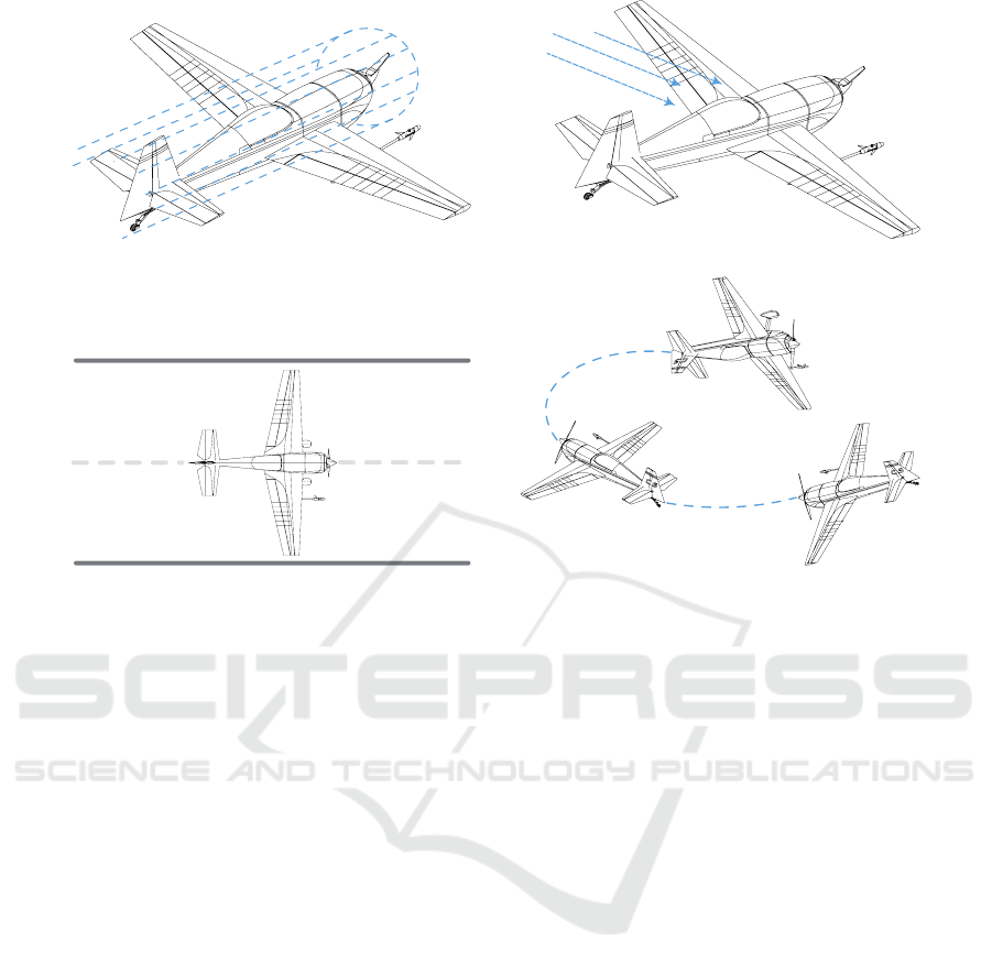
(a) Effect of the propeller induced slipstream;.
Wind
(b) Obstruction caused by the fuselage.
Take off Low airspeed
(c) Specific starting torque of the wind vane. (d) Rapid changes in airflow.
Figure 1: Factors influencing the accuracy of AOA/AOS sensor measurements.
combining wind vane sensors and angle estimation.
The flow angle estimation filters method is based on
the measured UAV airspeed, acceleration, and atti-
tude angle for fusion estimation. Complementary fil-
ters (Myschik et al., 2008), Kalman filters (Johansen
et al., 2015; Wenz et al., 2016), and extended Kalman
filters (Rhudy et al., 2013; Tian et al., 2018), etc.
have been proposed. The advantage of this method
is that it can realize AOA/AOS estimation without a
flow angle sensor, but there may be inevitable calcu-
lation delays when applied. Regarding engineering
applications, a redundant measurement method was
proposed to improve the above method, combining
wind vane sensors and angle estimation (Liu et al.,
2024). This method uses an onboard computer to
process the wind vane sensor measurement data and
realizes accurate estimation of AOA/AOS based on
the unscented Kalman filter (UKF). The robustness
of AOA/AOS measurement during UAV flight is im-
proved based on the real-time analysis and calculation
of the two data.
The above methods and results benefit the ap-
plication of AOA/AOS on small fixed-wing UAVs.
However, there are still several key issues that may
affect the measurement accuracy in engineering ap-
plications: (1) For UAVs with front-mounted pro-
pellers, the influence of propeller slipstream cannot
be avoided entirely when the sensor is installed on the
UAV fuselage; (2) Due to the installation position of
the sensor, when the UAV is in a hovering maneu-
vering state, the fuselage obstruction may affect the
accurate measurement of AOS; (3) Since the rotation
of the wind vane requires a specific starting torque
when the UAV is taxiing and flying at low speed, the
AOA/AOS measurement may fail; (4) When the UAV
performs continuous dynamic maneuvering flight, the
dynamic overshoot and oscillation of the wind vane
may occur due to the rapid change of airflow. The
specific scenarios illustrated in (1) to (4) are shown
in Fig. 1.
The key to solving these problems is researching
the error generation mechanism of wind vane probes
in small fixed-wing UAV applications and implement-
ing the perception, decision, and error correction of
the AOA/AOS measurement process based on multi-
condition process monitoring and fusion decision al-
gorithms. Among them, a potential solution is to
implement condition labeling for problems (1) to (4)
and design a dynamic adjustment mechanism for error
correction of wind vane sensor and angle estimation
redundant measurement method based on fusion de-
cision algorithms, thereby eliminating the hardware
measurement defects of wind vane sensors and fur-
ther improving the measurement accuracy of redun-
dant measurement methods in applications.
The main contribution of this paper could be cat-
ICEIS 2025 - 27th International Conference on Enterprise Information Systems
906
egorized into three aspects: (1) Motivated by (Liu
et al., 2024), a novel measurement method was de-
veloped for small fixed-wing UAVs, integrating data
acquisition using wind vane-based sensors with esti-
mation via the UKF algorithm; (2) For small fixed-
wing UAVs equipped with front-mounted propellers,
a detailed analysis was conducted to identify potential
factors impacting the measurement accuracy of sen-
sors installed beneath the wing; (3) To address inaccu-
racies in sensor measurements, an AOA/AOS fusion
method based on the adaptive network-based fuzzy
inference system (ANFIS) was proposed, leveraging
UKF-estimated values for compensation.
The remainder of this paper is structured as fol-
lows: Section 2 presents the design of the wind vane-
based sensor and the UKF-based AOA/AOS esti-
mation method. Section 3 investigates potential fac-
tors influencing the measurement accuracy of sen-
sors mounted beneath the wing and proposes an
AOA/AOS fusion method utilizing ANFIS. Section 4
presents the flight test conducted for data collection
and the simulation experiments designed to validate
the proposed data fusion approach. Finally, Section 5
provides a comprehensive summary of the study.
2 PRELIMINARY
Two approaches are available for recording AOA and
AOS. The first involves using the low-cost wind vane-
based AOA and AOS sensors. The second relies on
estimating AOA and AOS through the UKF algorithm
from inertial data.
2.1 Low-Cost AOA/AOS Sensors
A set of AOA and AOS sensors based on the rotation
of wind vane blades was employed to measure the α
and β angle (also known as AOA and AOS) during
the flight. The sensor housing features a streamlined
design and is fabricated using 3D printing with alu-
minum alloy. Inside the sensor, two brushless Hall
magnetic angle sensors are positioned perpendicular
to one another at a 90
◦
. Two carbon fiber wind vane
blades are affixed to the rotational axes of these sen-
sors, respectively. Additionally, a balancing block is
mounted on the symmetrical side of the wind vane to
ensure weight balance. The total weight of the sen-
sor assembly is approximately 25 g, with an encoder
resolution of 0.088
◦
.
When subjected to the incoming flow, the wind
vane blades drive the rotational axes of the angle sen-
sors. The phase and intensity of the rotational mag-
netic field are detected by monitoring the Hall ele-
ment array, enabling the measured values of the α
and β to be converted into digital signals and di-
rectly output via I2C communication. To mitigate
high-frequency noise resulting from engine vibration,
structure vibration, and mechanical nonlinearity dur-
ing sensor installation, the collected data are filtered
using the finite impulse response (FIR) method (Su-
laiman et al., 2022).
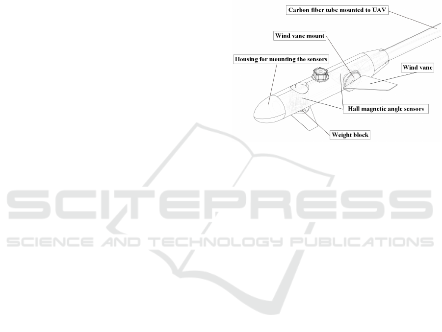
Figure 2: Structure of AOA/AOS sensors.
The sensor is connected to the UAV via a mount-
ing carbon tube that passes through the structural
housing. For UAVs with rear-mounted propellers, the
sensor can be installed on the nose of the UAV, provid-
ing direct access to undisturbed free airflow. This po-
sitioning helps avoid the effects of propeller-induced
airflow disturbances, thereby ensuring high data mea-
surement accuracy. However, for UAVs with front-
mounted propellers, the nose position becomes un-
suitable for sensor installation.
A feasible solution is to install the sensor beneath
one side of the wing, as illustrated in Fig. 3b. How-
ever, due to airflow disturbances caused by the pro-
peller and obstruction from the fuselage, this installa-
tion position inevitably affects the sensor’s measure-
ments and may even result in missing data.
2.2 AOA/AOS Estimation Method
In addition to the measurement from the AOA and
AOS sensors, the α and β can be estimated by fusing
inertial data collected by the flight controller. This
estimation process remains unaffected by the opera-
tional status of AOA/AOS sensors, making it a reli-
able and effective redundancy solution.
As an improvement of the extended Kalman filter,
the UKF offers superior accuracy for nonlinear distri-
bution statistics (Julier and Uhlmann, 1997). In this
paper, an estimation method based on the UKF was
adopted to estimate α and β using the inertial data.
The state estimation model for predicting the state at
An Adaptive Neuro-Fuzzy Inference Approach of AOA/AOS Data Fusion for Small Fixed-Wing UAV
907
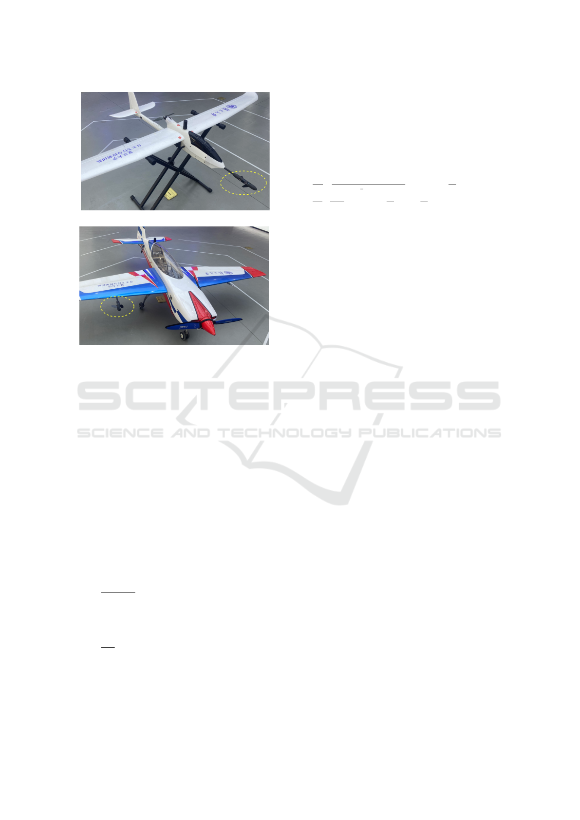
(a) At the nose;.
(b) Beneath the wing.
Figure 3: Two different installation configurations.
time step k using the state at time step k − 1 is defined
as:
X
k
= f (X
k−1
,u
k−1
) + w
k−1
Z
k
= h(X
k
,u
k
) + v
k
(1)
where w and v are the process and measurement
noise, respectively; the state vector X, the measure-
ment vector Z, and input vector u is defined as:
X = [α, β]
Z = [α, β]
u = [a
x
,a
y
,a
z
, p,q,r,θ,φ,V ]
(2)
where [a
x
,a
y
,a
z
] represents the three-axis accelera-
tion; [p,q,r] represents the three-axis angular veloc-
ity; θ and φ represent the pitch and roll angle, respec-
tively; and V represents the airspeed.
The state transition equation f (·) is:
˙
α =
1
mV cosβ
[−T sinα + mV(−pcos α sin β+
qcos β − r sin αsin β) + mg(sinα sin θ+
cosαcos φ cos θ) − L]
˙
β =
1
mV
[−T cosα sin β +Y − mV (−psin α+
r cos α) + mg(cos αsin β sinθ + cos βsin φ cos θ−
sinαsin β cos φcos θ)
(3)
where m represents the mass of the UAV; T , L, and
Y represent the thrust, lift, and side force of the UAV,
respectively.
The measurement vector Z is obtained using the
nonlinear measurement function f (·), which is de-
fined as:
Z = h(X, u,v) =
1
C
Lα
m(a
x
sinα−a
z
cosα)−T sinα
1
2
ρV
2
S
−C
L
0
−C
L
q
b
2V
q −C
L
δ
e
δ
e
1
C
Y
β
2ma
y
ρV
2
S
−C
Y
0
−C
Y
p
b
2V
p −C
Y
r
b
2V
r −C
Y
δ
α
δ
a
−C
Y
δ
r
δ
r
(4)
where ρ is the atmospheric density at sea level; b de-
notes the wing span; S denotes the wing area; C
L
∗
and
C
Y
∗
represent the lift and side force coefficients asso-
ciated with the parameter ∗ respectively.
3 METHOD
For small-sized UAVs with front-mounted propellers,
installing sensors beneath the wing is a practical
choice. However, this positioning inevitably com-
promises measurement accuracy. To mitigate this is-
sue, we proposed an ANFIS-based AOA/AOS data fu-
sion framework that leverages UKF-estimated values
to correct inaccuracies in sensor measurements.
3.1 Impact Factor Selection
In engineering applications, the precision of angle
sensors is often affected by many complex factors.
These elements encompass the flight conditions of the
UAV, the physical characteristics of sensors, and their
positioning during installation. The effects of these
factors on measurement accuracy are interconnected
and cannot be clearly expressed in mathematical for-
mulas, which augment the intricacy of the measure-
ment system.
To better understand and address these impact fac-
tors, this study abstracts them into three key physical
quantities, airspeed, yaw angle, and sensor status, that
can be measured and used as inputs to the ANFIS es-
timation model. Each of these factors affects the AOA
and AOS measurements through distinct mechanisms.
Airspeed is a crucial factor impacting sensor accu-
racy. It is generally accepted that the AOA/AOS sen-
sor typically has a minimum operational airspeed of
10m/s. If the airspeed falls below this threshold, the
sensor either fails to activate or produces unreliable
measurements. Also, if the airspeed is too high, rapid
airflow changes may cause the wind vane to overshoot
or oscillate, thereby reducing measurement accuracy.
Flight yaw angle variations typically occur during
UAV maneuvers, such as turns or spirals. In these
ICEIS 2025 - 27th International Conference on Enterprise Information Systems
908
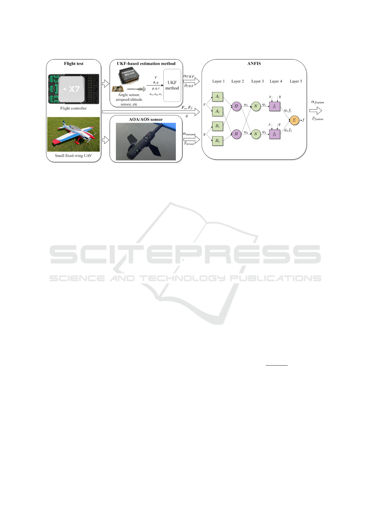
Figure 4: ANFIS-based AOA/AOS fusion approach.
cases, due to the fuselage’s blocking effect, the sen-
sor cannot be able to accurately detect the direction
and speed of airflow, especially leading to errors in
AOS measurements. By continuously monitoring the
flight yaw angle, these errors can be identified and
corrected in real-time, improving the accuracy of an-
gle measurements.
Sensor malfunctions, in this study, were catego-
rized into two types: null value faults (denoted as
1) and extreme value faults (denoted as 2). Extreme
value faults typically occur when AOA exceeds ±20
◦
or AOS exceeds ±60
◦
, while null value faults indicate
that the sensor fails to provide valid data, often return-
ing a NaN. In such cases, the reliability of the sensor’s
data is compromised. The sensor is expected to pro-
vide relatively valid measurement data only when it is
in a normal operating state (denoted as 0).
In designing the ANFIS model based on actual
flight data, the three key factors mentioned above, air-
speed, yaw angle, and sensor malfunction type, along
with the sensor’s output and the estimation from the
UKF algorithm, are utilized as inputs to the ANFIS
system. This approach enables the simulation of vari-
ous error sources present in real measurement scenar-
ios and makes full use of prior knowledge to enhance
the accuracy of AOA and AOS measurements.
3.2 AOA/AOS Fusion Method
Considering the interference effects analyzed above,
we proposed a novel data fusion approach based on
the ANFIS. This approach utilizes the UKF-estimated
AOA and AOS to compensate for the AOA/AOS sen-
sor measurements affected by the disturbances.
As a combination of fuzzy logic and artificial neu-
ral networks, ANFIS combines the learning ability
and relational structure of the artificial neural net-
works with the fuzzy logic’s decision-making mech-
anism (Jang, 1993). Benefiting from the fuzzy
inference system embedded in its network struc-
ture, ANFIS effectively addresses the issue of non-
interpretable weight values commonly found in other
artificial neural networks. As a result, it has been ex-
tensively utilized in addressing a wide range of com-
plex problems (Karaboga and Kaya, 2019; Guerra
et al., 2024).
To facilitate understanding of its principle, con-
sider a case where ANFIS has two inputs (x,y) and
one output f . Notably, it can be readily generalized to
scenarios involving more inputs. The network struc-
ture of ANFIS comprises five layers.
The first layer, known as the fuzzification layer,
transforms the input values (x, y) into fuzzy clusters
defined by Gaussian membership functions, which
can be expressed as:
(
Q
1
i
= µ
A
i
(x) i = 1,2
Q
1
i
= µ
B
i−2
(x) i = 3,4
(5)
where Q
1
i
represents the membership grades of node
i in the fuzzification layer; µ
A
i
(·) and µ
B
i−2
(·) repre-
sent Gaussian membership functions of x in the cor-
responding fuzzy cluster, which is:
µ
k
(x) = exp
−
(x − c
k
)
2
2σ
2
k
(6)
where c
k
is the center of the Gaussian function, and
σ
k
is the standard deviation that controls the width of
the cluster.
The second layer, referred to as the rule layer,
computes the firing strengths w
i
of the rules by mul-
tiplying the membership grade values obtained in the
fuzzification layer:
O
2
i
= w
i
= µ
A
i
(x) · µ
B
i−2
(x) i = 1,2 (7)
The third layer, referred to as the normalization
layer, scales the firing strengths of each rule to ensure
An Adaptive Neuro-Fuzzy Inference Approach of AOA/AOS Data Fusion for Small Fixed-Wing UAV
909
proportional consistency. The normalized value for
the i-th rule is:
O
3
i
= ¯w
i
=
w
i
∑
4
j
w
j
i ∈ 1,2,3,4 (8)
The fourth layer, referred to as the defuzzification
layer, calculates the weighted value of each rule at
each node. This value is determined by a first-order
polynomial:
O
4
i
= ¯w
i
f
i
= ¯w
i
(p
i
x + q
i
y + r
i
) i ∈ 1,2, 3, 4 (9)
where (p
i
,q
i
,r
i
) is called the consequence parame-
ters. The dimension of consequence parameters is one
more than that of input states.
The fifth layer, known as the summation layer,
generates the final output by summing the weighted
values calculated in the defuzzification layer:
O
5
i
=
∑
i
¯w
i
f
i
=
∑
i
w
i
f
i
∑
i
w
i
(10)
The training algorithm employed in this paper uti-
lizes a hybrid method that combines two distinct opti-
mization techniques: backpropagation for optimizing
the parameters associated with the input membership
functions and least squares estimation for optimizing
the parameters associated with the output member-
ship functions.
4 EXPERIMENTS AND RESULT
The small fixed-wing UAV used in the flight test
was EXTRA 300 NG, with its specification available
in (Liu et al., 2024). The AOA/AOS sensors were
installed on the right wing because of its forward pro-
peller. A CUAV X7+ flight controller on the UAV
platform collects data from the IMU, GPS, electronic
compass, airspeed sensor, and other units. Specifi-
cally, an onboard Raspberry Pi recorded the AOA and
AOS during the flight.
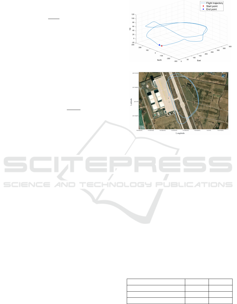
The flight test lasted approximately 2 min. During
this period, the UAV followed pre-defined waypoints,
automatically performing climbing, cruising, maneu-
vering, and descent. [a
x
,a
y
,a
z
], [p,q, r], [ψ,θ,φ],
[δ
a
,δ
e
,δ
r
], and V were recorded using the CUAV X7+
flight controller, while α and β were recorded by the
AOA/AOS sensor on the right wing. The flight test
trajectory is illustrated in Fig. 5.
In this paper, the ANFIS was employed by Matlab
R2024a. The computer configuration employed in-
cludes a 12th Gen Intel(R) Core(TM) i9-12900H pro-
cessor running on a Windows 11 operating system.
The approach is shown in Fig. 4.
AOA and AOS were treated separately, with a cor-
responding ANFIS developed for each angle. Taking
(a) Three-dimensional flight trajectory;.
(b) Two-dimensional plane trajectory.
Figure 5: Flight test trajectory.
AOA as an example, the inputs to the network are the
AOA sensor measurement
ˆ
α
sensor
, the AOA estimate
from UKF
ˆ
α
UKF
, airspeed V , the yaw angle ψ, the
fault type of AOA sensor F
α
; and the output is the
actual value of AOA. Each input variable is associ-
ated with eleven Gaussian membership functions, and
the output layer employs a linear relationship, where
the outputs from all fuzzy sets are aggregated through
weighted summation to produce the final prediction.
70 % of the data were randomly sampled from the
original dataset and designated as the training set. Af-
ter normalization, the data was fed into the ANFIS.
The error tolerance was set to 10
−8
, and the epochs
were set to 300.
As illustrated in Fig. 6 and Fig. 7, comparisons of
the fusion values of ANFIS with the actual values are
demonstrated for both AOA and AOS testing sets. Ta-
ble 1 provides a statistical analysis.
Table 1: Statistical analysis of ANFIS fusion results.
AOA AOS
Average Relative Error 10.26 % 12.77 %
Root Mean Square Error 0.652
◦
0.542
◦
Correlation Coefficient 0.912 0.891
The performance of ANFIS data fusion for the
AOA and AOS of the selected UAVs was evaluated
using test datasets. The results indicate that ANFIS
can effectively predict the actual values by integrating
ICEIS 2025 - 27th International Conference on Enterprise Information Systems
910
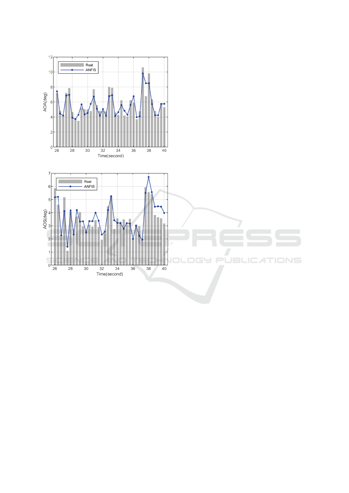
Figure 6: Fusion results of AOA.
Figure 7: Fusion results of AOS.
sensor measurements and UKF estimates, taking into
account various influencing factors. The average rel-
ative error between the predicted and actual values of
the ANFIS model proposed in this paper is less than
15 %, with the average relative errors being 10.26 %
for AOA and 12.77 % for AOS. These results demon-
strate that the proposed method can effectively incor-
porate prior knowledge and account for the influenc-
ing factors, thus providing accurate fusion results that
meet the application requirements.
5 CONCLUSION
This paper proposes a novel and intelligent error
correction method for wind sensors measuring AOA
and AOS in small fixed-wing UAVs. The proposed
method utilizes the ANFIS framework. The study
identifies the main measurement error sources as sen-
sor null/extreme faults, airframe occlusion, and too
low/too high airspeed. The proposed mechanism em-
ploys an adaptive correction process to address sys-
tem faults by leveraging actual sensor measurements,
UKF estimates, and error sources to generate more
precise angle fusion results. Numerical experiments
demonstrate that the system employing this architec-
ture effectively mitigates the hardware measurement
defects of the wind vane sensor, with an average rel-
ative error of less than 15 %, which falls within the
acceptable margin.
In future research, we plan to include more com-
plex sensor failure scenarios. Furthermore, the study
will investigate real-time dynamic tuning algorithms
to improve the measurement accuracy of redundant
measurement methods for small UAVs.
REFERENCES
Data, S. A. (Accessed: 24-Dec-2024). Smv-
1 flow vane. Online: https://www.swiss-
airdata.com/products/flow-vanes/smv-1.
Guerra, M. I., de Ara
´
ujo, F. M., de Carvalho Neto, J. T.,
and Vieira, R. G. (2024). Survey on adaptative neu-
ral fuzzy inference system (anfis) architecture applied
to photovoltaic systems. Energy Systems, 15(2):505–
541.
Jang, J.-S. (1993). Anfis: adaptive-network-based fuzzy in-
ference system. IEEE transactions on systems, man,
and cybernetics, 23(3):665–685.
Johansen, T. A., Cristofaro, A., Sørensen, K., Hansen, J. M.,
and Fossen, T. I. (2015). On estimation of wind veloc-
ity, angle-of-attack and sideslip angle of small uavs
using standard sensors. In 2015 International Confer-
ence on Unmanned Aircraft Systems (ICUAS), pages
510–519. IEEE.
Julier, S. J. and Uhlmann, J. K. (1997). New extension of the
kalman filter to nonlinear systems. In Signal process-
ing, sensor fusion, and target recognition VI, volume
3068, pages 182–193. Spie.
Karaboga, D. and Kaya, E. (2019). Adaptive network based
fuzzy inference system (anfis) training approaches: a
comprehensive survey. Artificial Intelligence Review,
52(4):2263–2293.
Liu, Y., Wang, Y., Wang, L., Li, H., and Ai, J. (2024). De-
velopment of a low-cost aoa/aos sensor and data pro-
cessing system for small-sized uavs. In 2024 IEEE
19th Conference on Industrial Electronics and Appli-
cations (ICIEA), pages 1–6. IEEE.
Myschik, S., Holzapfel, F., and Sachs, G. (2008). Low-cost
sensor based integrated airdata and navigation sys-
tem for general aviation aircraft. In AIAA Guidance,
Navigation and Control Conference and Exhibit, page
7423.
Prem, S., Sankaralingam, L., and Ramprasadh, C. (2020).
Pseudomeasurement-aided estimation of angle of at-
An Adaptive Neuro-Fuzzy Inference Approach of AOA/AOS Data Fusion for Small Fixed-Wing UAV
911

tack in mini unmanned aerial vehicle. Journal of
Aerospace Information Systems, 17(11):603–614.
Rhudy, M. B., Larrabee, T., Chao, H., Gu, Y., and Napoli-
tano, M. (2013). Uav attitude, heading, and wind esti-
mation using gps/ins and an air data system. In AIAA
guidance, navigation, and control (GNC) conference,
page 5201.
Sankaralingam, L. and Ramprasadh, C. (2020). A com-
prehensive survey on the methods of angle of attack
measurement and estimation in uavs. Chinese Journal
of Aeronautics, 33(3):749–770.
Sulaiman, I. A., Hassan, H. M., Danish, M., Singh, M.,
Singh, P., and Rajoriya, M. (2022). Design, compar-
ison and analysis of low pass fir filter using window
techniques method. Materials Today: Proceedings,
49:3117–3121.
Tian, P., Chao, H., Flanagan, H. P., Hagerott, S. G., and Gu,
Y. (2018). Design and evaluation of uav flow angle
estimation filters. IEEE Transactions on Aerospace
and Electronic Systems, 55(1):371–383.
Wang, L., Li, H., Liu, Y., and Ai, J. (2023). Design and real-
ization of a cable-drogue aerial recharging device for
small electric fixed-wing uavs. In 2023 International
Conference on Unmanned Aircraft Systems (ICUAS),
pages 926–932. IEEE.
Wenz, A., Johansen, T. A., and Cristofaro, A. (2016). Com-
bining model-free and model-based angle of attack es-
timation for small fixed-wing uavs using a standard
sensor suite. In 2016 International Conference on
Unmanned Aircraft Systems (ICUAS), pages 624–632.
IEEE.
ICEIS 2025 - 27th International Conference on Enterprise Information Systems
912
