
Iterative Diagnosis-Driven Augmented Generation (IDDAG) for
Programmatic 3D CAD
Thomas Paviot
1
a
, Virginie Fortineau
1 b
and Samir Lamouri
2,3 c
1
meeDIA, 15 rue Glais Bizoin, 35000 Rennes, France
2
Arts & M´etiers, 151 bd de l’Hˆopital, 75013 Paris, France
3
LAMIH CNRS, Universit´e Polytechnique Hauts-de-France, Campus Mont Houy, 59313 Valenciennes Cedex 9, France
Keywords:
CAD, 3D, LLM, Context Augmentation, BRep.
Abstract:
This paper presents a novel approach for automated generation of 3D CAD models using Large Language
Models (LLMs) within Model-Based Systems Engineering workflows. We introduce Iterative Diagnosis-
Driven Augmented Generation (IDDAG), a methodology combining programmatic geometry creation with
systematic diagnostic feedback. The approach leverages a dedicated API for exact Boundary Representation
(B-Rep) geometry generation, augmented by a closed-loop architecture that provides iterative refinement based
on syntactic, runtime, and geometric analysis. Unlike existing methods requiring extensive training datasets
or producing approximate geometries, our solution generates t opologically valid, parameterized models while
maintaining traceability to engineering requirements. Results demonstrate progressive geometric refinement
across iterations, with the diagnostic feedback mechanism effectively identifying and correcting topological
inconsistencies.
1 INTRODUCTION
In the context of Indu stry 4.0’s digitalization of in-
dustrial value chains, the integration between Model-
Based System Engineering (MBSE) a nd Computer-
Aided De sig n (CAD) becomes essential to facilitate
the digitization of physical product development pro-
cesses (Meussen, 2021).
3D CAD mode ls are particularly critical as they
represent the exact geometric definition that will be
used throughout the product lifecycle, at each stage
of the digital c hain (visualization, simula tion, au to-
mated manufacturing, etc.). Integrating 3D rep resen-
tation w ithin an MBSE approach ther e fore imposes
stringent requirements: models must comply with
structural and semantic consistency constraints with
other system views (functio nal, logical, physical ar-
chitectures); their c onstruction must follow a tr ace-
able process, where each design choice can be jus-
tified against initial req uirements; their maintenance
over tim e requires precise and unambiguous parame-
terization enabling adaptation to evolving needs. Cre-
a
https://orcid.org/0000-0002-3380-8845
b
https://orcid.org/0000-0001-7043-4849
c
https://orcid.org/0000-0003-3868-9280
ating these 3D models requ ires significant technical
expertise, substantial tim e investment, and the use of
complex professional CAD software - making these
costly processes.
Concurrently, the development of Large Language
Models (LLMs) reveals rema rkable opp ortunities in
the Industry 4.0 domain (Bourdin et al., 2024).
This paper thu s aims to address two research ques-
tions: is it possible, using LLMs, to automa te all or
part of the process of creating 3 D models from a set of
requirements? If so, how can w e ensure the explain-
ability of the provided solution to enable validation of
choices and theref ore design traceability? Industrial
3D CAD processes utilize Boundary Representation
(B-Rep), as it offers mathematically exact geometry
representation. While recent AI advances have en-
abled notable progress in p rocessing appro ximate ge-
ometries (particularly through meshes) with applica-
tions in entertainment, visualization, and 3D printing,
research concern ing exact representation remains less
numerous and advanced.
As a consequence, the paper is structured as fol-
lows: Section 2 presents the state of the art regarding
LLM utilization for B-Rep generation and its current
limitations. Section 3 introduces our two scientific
contributions: a programmatic metho dology coupled
474
Paviot, T., Fortineau, V. and Lamouri, S.
Iterative Diagnosis-Driven Augmented Generation (IDDAG) for Programmatic 3D CAD.
DOI: 10.5220/0013443500003896
Paper published under CC license (CC BY-NC-ND 4.0)
In Proceedings of the 13th International Conference on Model-Based Software and Systems Engineering (MODELSWARD 2025), pages 474-480
ISBN: 978-989-758-729-0; ISSN: 2184-4348
Proceedings Copyright © 2025 by SCITEPRESS – Science and Technology Publications, Lda.

with an iterative context enrichment mechanism f or
solution quality improvement. Section 4 details the
experimental validation protocol and results. Fina lly,
Section 5 discusses the contributions relative to ex-
isting approaches and identifies future research direc-
tions.
2 RELATED WORK
2.1 B-Rep Model
The BRep model describes the mathematically exact
geometry of a component through non-volumetric e l-
ements that com pose its surface. These elements c on-
sist of faces, edges, and vertices arranged in an adja-
cency graph. A face corresponds to a surface patch, an
edge to an intersection curve segment between at least
two surfaces, and a vertex to an intersection point be-
tween two distinct curves (Mor tenson, 1997).
2.2 Large Language Models
A Large Language Model (LLM) is an artificial in-
telligence system based on a transformer architecture,
trained on massive volumes of textual data (ranging
from hundreds of billions to several trillion tokens)
for self-supervised learn ing purposes. The se models
are cap able of Natural Language Processing (NLP)
and can perform various complex linguistic and cog -
nitive tasks suc h as translation, reasoning, program-
ming, and pr oblem-solving, either in few-shot mode
(with few examples) or zero-sh ot mode (without ex-
amples). Their lea rning capacity e merges from at-
tention mechanisms allowing them to capture long-
term dep e ndencies in textual seq uences and acquire
sophisticated contextual representatio ns of language
(Naveed et al., 2024).
Regarding coding tasks, (Liang et al., 2024) re-
veal that LLMs demonstrate their greatest efficiency
when tasks are structured with clear context, for ex-
ample targeted mo difications of existing code, data
visualization tasks, o r documented API implementa-
tion. Efficiency is maximized when source code is
available as context, objectives are well- defined, and
the user possesses sufficient technical expertise to for-
mulate precise queries.
2.3 LLMs for B-Rep Geometry
Generation
In the field of automatic BRep geometry generation,
scientific literatu re works can be classified in to two
categories: a) those that directly produce BRep g e-
ometry; b) tho se that produce an intermediate artifact
that drives geometry creation.
B-Rep Geometry Generation. This approach is
chosen, fo r example, by ( Xu et al., 2024) (Zhang
et al., 2023) (Zhang et al., 2024). The algorithm gen-
erates a graph representing BRep topology and ge-
ometry. These approac hes use neural networks, but
not directly LLMs. A preliminary learning phase is
necessary, involving datasets of several hundred or
thousand examples. Then validation tests are per-
formed on data not included in the initial dataset.
These works face issues of precision , explainability,
and lack of formal guarantees on the production of
topologically valid CAD models (risks of generat-
ing non-manifold geometries, or surfaces with self-
intersections).
Indirect Generation. (Wu et al. , 202 3) introduce
CAD-MLLM, a system using multimodal LLMs
(text, image) to gen erate CAD models from various
inputs (text, ima ges, point clouds). In this case, ge-
ometry is not directly generated by the LLM: the out-
put is a geometry description in the form of a ”com-
mand sequence,” which drives geometry construction
(a method th a t falls within the framework of Para-
metric Macro Approaches introduced by (Mun et al.,
2003)). Each sequence element is identified by a
mnemonic associated with a token in the fine-tuning
phase of the chosen LLM. According to the authors,
CAD-MLLM presents the following limitations: the
description in the form of basic op eration sequences
uses an ad hoc model composed of a small number of
operations in linear form. It is work centere d on exact
geometry reconstruction, but not generation from re-
quirements. (Yuan et al., 2024) Zhang et al. propose a
very similar approach and report the same limitations.
2.4 Open Issues
We identify three significant barriers in the presented
works:
• all works rely on a learning phase based on a large
dataset, which is a costly operation,
• produced geometries are limited to simple cases,
• it is not p ossible to guarantee the topological va-
lidity of generated shapes.
Finally, we note that in these works, geometry is never
related to the notions of function or requirement so
important in MBSE. In the remainder of this paper,
we propose a method to address the preceding barri-
ers.
Iterative Diagnosis-Driven Augmented Generation (IDDAG) for Programmatic 3D CAD
475

3 PROGRAMMATIC APPROACH
FOR BRep GENERATION
We therefore orient our work toward an approach that:
• ge nerates para meterized geometry programmati-
cally (see section 3.1), enabling for instance the
creation of component catalo gs with complex ge-
ometries, or inclusion in simulation optimization
loops (e.g., FEM),
• ge nerates exact, topologically consistent geome-
try,
• does not requir e LLM fine-tuning or learning, nor
datasets. We prefer context augmentation .
3.1 Programmatic Approach
Principle. Following from the previous section, we
propose a path that falls within the ”in direct gen-
eration” category of geometry, different fr om those
proposed in section 2: a ”progr ammatic” approach.
Rather than asking th e LLM to generate a command
sequence in an ad hoc model, we propose asking it to
generate a computer program to which form creation
is delegated. Two approaches can be con sidered:
• de sign a Domain Specific Language for 3D form
programming;
• use a common programming languag e
(JavaScrip t, Java, C, etc.) and a domain-specific
3D development library.
The design and implementation of a DSL present
two challenges: with its specific grammar, it re-
quires L LM fine-tuning, and thus the creation of a
sufficiently large dataset to ensure pro per learning.
Additionally, a com piler or interpreter fo r this DSL
must be developed. To overcome these difficu lties,
we choose the Python programming language in this
work.
Example and Limitations. To illustrate this ap-
proach , here is a basic ChatGPT prompt to generate
a 3D nut using Python and the free and open-source
3D CAD library pythonocc (Paviot, 2022) :
Write a python script, based on the pythonocc
library, to generate the parameterized 3D
geometry of a standard H-M10 nut.
The generated program is included in Appendix 1.
We observe that:
• the program is difficult for humans to read, except
for library specialists;
• the program, when executed, generates an error:
the BRepBuilderAPI MakePrism class does not
exist in the library, it is an LLM hallucination.
This pro grammatic approach shows its limitations
on a simple example: ChatGPT has only limited
knowledge of the utilized library and proposes a non-
existent class.
Dedicated API. To gain explainability, we seek to
obtain a m ore concise and clearer program. We pro-
pose relying on a dedicated API based on:
• a taxo nomy of elementary operations for creation,
transformation, and measurement of basic shapes
• a naming convention fo r classes and functions
methods tha t is closest to natural language. This
proxim ity to natural language improves program
readability for hum ans;
Furthermore, we propose passing textual API doc-
umentation to the LLM. This co ntextual elemen t
should enable the LLM to generate a progra m con-
forming to the provided specification, addressing the
problem raised in the previous section. The documen-
tation must be concise, to limit prompt le ngth, and
exhaustive to cove r all proposed functionalities.
3.2 Context, Metadata, Requirements,
and Knowledge
Context The structure of the prom pt passed to the
LLM is therefore:
<instructions>[...]</instructions>
<api_documentation>[...]</api_documentation>
For example:
<instructions>
Generate a Python script to create the 3D
geometry of an H-M10 nut, using the library
whose documentation is given below
</instructions>
<api_documentation>
3D Modeling Library
=================
This API allows easy creation and manipulation
of 3D geometric objects.
[...]
</api_documentation>
Requirements and Knowledge. Requirements are
part of the prompt passed to the LLM, enclosed in
<requirements></requirements>
tags. Specifica-
tions are of three types:
• functional requ irements (maximu m dimensions,
maximum mass)
MBSE-AI Integration 2025 - 2nd Workshop on Model-based System Engineering and Artificial Intelligence
476

• technical requir e ments (technology used, mater i-
als, etc.)
• various a dditional requirements (expected level of
detail, aesthetics, etc.)
Requirements are passed as text, which can rep-
resent structured (JSON, XML), semi-structured, or
unstructured information (natu ral language) depend-
ing on the context. Similarly, domain-specific knowl-
edge is passed between
<knowledge></knowledge>
tags. For example, this could be an excerpt from the
standard specifying H-M1 0 nut dimensions. Thus, the
final structure of the prompt passed to the LLM looks
like (replace the
#component
token with any compo-
nent name, for example
H-M10 nut
):
<instructions>
Write a Python program to generate
the parameterized 3D geometry of a #component:
- using the API whose documentation is given
below
- using #component metadata
- using the given knowledge elements
- respecting all listed requirements
</instructions>
<metadata>[...]</metadata>
<api_documentation>[...]</api_documentation>
<knowledge>[...]</knowledge>
<requirements>[...]</requirements>
The Python program generated this way offers better
human readability and creates th e following graphical
3D geometry (see 1):
Figure 1: Fixed 3D nut generation.
4 DIAGNOSIS-DRIVEN
AUGMENTED GENERATION
Despite the precautions taken previously (dedicate d
API, concise docume ntation in context), output qual-
ity cannot be guaranteed: the generated program may
still present syntactic errors, the geometry creatio n
may prove mathematically un feasible, or the geom-
etry may be topologically incorrect. To ad dress these
deficiencies and enhance reliability, we pro pose aug-
menting the LLM with reflective capabilities by pro-
viding a set of information constructed a posteriori,
based on the LLM output. This involves e nriching the
LLM prompt context with a diagnostic r eport com-
prising information on:
• syntactic compliance of the generated progr a m,
utilizing static code analysis tools
• program execution success a nd geometry cre-
ation, derived fr om Python console output
• analysis of the produce d geometry (topological
coherence, inertial elements, bounding volume,
etc.), performed by a dedicated software compo-
nent
The generated diagnosis thus comprises th ree dis-
tinct sectio ns:
<diagnosis>
<static_analysis>[...]</static_analysis>
<runtime_analysis>[...]</runtime_analysis>
<geometric_analysis>[...]</geometric_analysis>
</diagnosis>
Once th is diagnostic report is generated, it is
added to the context and returned to th e LLM for po-
tential modification requests. This process iterates un-
til a satisfactory response is obtained, with the user
determining whether to initiate a new generation cy-
cle. Thus, during successive iterations, the prompt
passed to the LLM the second time (after the first it-
eration) follows this schematic XML model:
<input>
<instructions>[...]</instructions>
<metadata>[...]</metadata>
<api_documentation>[...]</api_documentation>
<knowledge>[...]</knowledge>
<requirements>[...]</requirements>
</input>
<output>[... first LLM response ...]</output>
<diagnosis>
<static_analysis>[...]</static_analysis>
<runtime_analysis>[...]</runtime_analysis>
<geometric_analysis>[...]</geometric_analysis>
</diagnosis>
<input>
<instructions>Given the diagnostic report,
update the 3D generation code.
</instructions>
</input>
After the second iteration, the following is added
to the previous prompt:
<output>[... second LLM response ...]</output>
<diagnosis>
<static_analysis>[...]</static_analysis>
<runtime_analysis>[...]</runtime_analysis>
<geometric_analysis>[...]</geometric_analysis>
</diagnosis>
<input>
<instructions>Given the second diagnostic
report, update the 3D generation code.
</instructions>
</input>
Iterative Diagnosis-Driven Augmented Generation (IDDAG) for Programmatic 3D CAD
477

and so forth. This workflow process can be il-
lustrated by the synoptic diagram in Figure 2, which
adopts closed-loop control system semantics.
5 EXPERIMENTS
The experimen ta l validation was c onducted using
Python 3.10 and the latest pythonocc version. The
Large Language Model used was Claude Haiku, se-
lected fo r its balance of performance and response
speed. Two distinct test cases were implemented to
evaluate the IDDAG methodology: a standardized
mechanical component (ball bearing) and an aerody-
namic surface (airplane wing). For each experiment,
we analyze the geometric evolution across successive
iterations and examine convergence characteristics.
Ball Bearing. The first experim e nt focused on gen-
erating a 6203-series radial ball bearing , chosen for
its well- defined geometric constraints and standard-
ized dimensions. This is the only requirement.
Tab le 1 illustrates the geometric evolution across
five iterations. Initial generation (n=1) pr oduced a
simplified cylindrical representation lacking internal
components. Subsequent iterations progressively re-
fined the model: n=2: Addition o f basic rolling el-
ement placeholders, n=3: Implementatio n of correct
race profiles, n=4: Refinement of ball ge ometry and
spacing n=5: Final optimization of contact surfaces
and clearances.
The diagnostic fe edback loop identified and cor-
rected multiple issues, including topological inconsis-
tencies in race-to-ball interfaces (n=2→n=3) and ge-
ometric valid ity constraints for rolling element distri-
bution (n=3→n=4). 1
Airplane Wing. The second experiment involved
generating an aircraft win g section using the NACA
0012 airfoil profile, chosen for its well-documented
geometry and extensive validation data. The sp ec-
ification included a 1000m m span, 200mm chor d
length, and pr ecise adherence to the NACA 0012 co-
ordinate system. The evolution shown in Table 2
demonstra te s sign ificant challen ges in initial geom-
etry creation: n=1: Failed mathema tica l generation
of intrados and extrados curves (not visualized), n=2:
Successfully generated planar surface but incorrect
extrusion direction, n=3: Corrected extrusion vector
orientation, resulting in topologically and geometri-
cally valid 3D form.
Discussion. The experimen tal results demonstrate
iterative geometric refinement across successive gen-
erations, though convergence is not consistently
achieved for all test cases. The ball bearing example
exhibited systematic improvement in geometric accu-
racy and topological validity over 5 iteratio ns, pro-
gressing from a simplified cylindrical representation
to a complete mode l with prope r race profiles and
ball spacing . In contrast, the aircraft wing case high-
lighted po tential lim itations, requ iring only 3 iter a -
tions but encountering initial mathematical generation
failures before achieving a valid 3D form. These pre-
liminary findings, while promising, warrant further
validation across a broader range of mechanical com-
ponen ts to comprehensively assess the m ethodology’s
robustness and generalizability. The results also sug-
gest that targeted human intervention, through man-
ual augmentation of diagnostic feedback, may en-
hance convergence b y redirecting suboptimal initial
design choices. Additio nal experimentation is needed
to evaluate the approach’s scalability to more com-
plex geometries and to establish quantitative metrics
for convergence behavior.
6 CONCLUSION AND
PERSPECTIVES
This paper presented two scientific contributions en-
abling 3D geometry gener ation using Large Language
Models:
• A programmatic approach using a dedicated API
for geometry creation
• A closed-loop architecture for context augmen-
tation, termed Iterative Diagnosis-Driven Aug-
mented Generation (IDDAG)
This solution offers key a dvantages: without
requirin g extensive training or fine-tuning, it pro-
duces human-readable, explainable, and par ameter-
ized models that generate topologically valid geome-
tries. The 3D artifact gene ration maintains trace-
ability to requirements and refines throu gh itera-
tions. The proposed methodology has been imple-
mented and validated on elementary test cases. Short
term resear ch directio ns include formal analysis of
convergence proper ties and optimization of iteration
counts, mor e complex geometries and extension to
complex assemblies with multiple interacting compo-
nents. The diagnostic-driven augmentation approach
shows potential for transposition to oth er design do-
mains where systematic f eedback can be generated.
Mid to long-term researc h priorities include e stablish-
ing forma l co nvergence guaran te e s, evaluating sys-
MBSE-AI Integration 2025 - 2nd Workshop on Model-based System Engineering and Artificial Intelligence
478
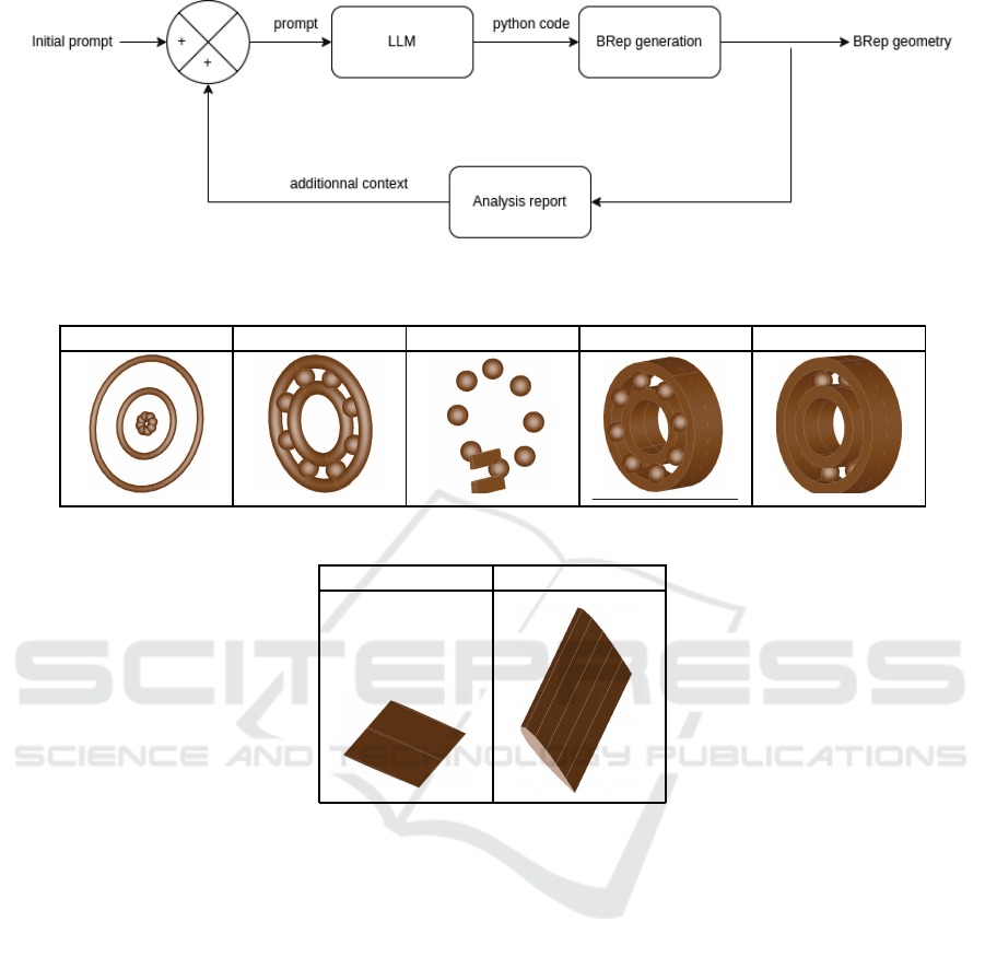
Figure 2: Closed-loop architecture of the Iterative Diagnosis-Driven Augmented Generation (IDDAG) system.
Table 1: Ball Bearing: Geometric Evolution Across Iterations.
n = 1 n = 2 n = 3 n = 4 n = 5
Table 2: Aircraft Wing: Geometric Evolution Across Iterations.
n = 2 n = 3
tem scalability for complex assemblies, and develop-
ing r obust integration protocols with established CAD
workflows.
REFERENCES
Bourdin, M., Neumann, A., Paviot, T., Pellerin, R., and
Lamouri, S. ( 2024). Exploring the applications of
natural language processing and language models for
production, planning, and control activities of SMEs
in industry 4.0: a systematic literature review. Jour-
nal of Intelligent Manufacturing.
Liang, J. T., Yang, C., and Myers, B. A. (2024). A large-
scale survey on the usability of ai programming as-
sistants: Successes and challenges. In Proceedings of
the 46th IEEE/ACM International Conference on Soft-
ware Engineering.
Meussen, B. (2021). On the use of model based systems
engineering and CAD for the design of physical prod-
ucts. Proceedings of the Design Society, 1:2317–
2326.
Mortenson, M. E. (1997). Geometric modeling. John Wiley
& Sons, Inc.
Mun, D., Han, S., Kim, J., and Oh, Y. (2003). A
set of standard modeling commands for the history-
based parametric approach. Computer-Aided Design,
35(13):1171–1179.
Naveed, H., Khan, A. U., Qiu, S., Saqib, M., Anwar, S., Us-
man, M., Akhtar, N., Barnes, N., and Mian, A. (2024).
A comprehensive overview of large language models.
Paviot, T. (2022). pythonocc.
Wu, S., Khasahmadi, A., Katz, M., Jayaraman, P. K., Pu, Y.,
Willis, K., and Liu, B. (2023). CAD-LLM: Large lan-
guage model for CAD generation. In NeurIPS 2023
Workshop on Machine Learning for Creativity and
Design.
Xu, X., Lambourne, J., Jayaraman, P., Wang, Z., Willis, K.,
and Furukawa, Y. (2024). Brepgen: A b-rep genera-
tive diffusion model with structured latent geometry.
ACM Transactions on Graphics, 43(4).
Yuan, Z., Shi, J., and Huang, Y. (2024). OpenECAD: An
efficient visual language model for editable 3D-CAD
design. Computers & Graphics, 124.
Zhang, C., Pinqui´e, R., Polette, A., Carasi, G., De Char-
Iterative Diagnosis-Driven Augmented Generation (IDDAG) for Programmatic 3D CAD
479

nace, H., and Pernot, J.-P. (2023). Automatic 3D CAD
models reconstruction fr om 2D orthographic draw-
ings. Computers & Graphics, 114:179–189.
Zhang, C., Polette, A., Pinqui´e, R., Carasi, G., De Char-
nace, H., and Pernot, J.-P. (2024). eCAD-Net: Ed-
itable parametric CAD models reconstruction fr om
dumb B-Rep models using deep neural networks.
Computer-Aided Design, 178.
APPENDIX
1
from OCC . Core . BRep Build erAP I impor t
BRep Buil d erAP I_Mak e Po lygon ,
BRep Buil d erAP I_Mak eFace ,
BRep Buil d erAP I_Mak ePri sm
2
from OCC . Core . BRep PrimA PI imp ort
BRep Prim A PI_M akeCy lind er
3
from OCC . Core . BRep AlgoA PI imp ort
BRep Algo A PI_C ut
4
from OCC . Core . gp i m port gp_Pnt ,
gp_Vec , gp_Ax2 , gp _Dir
5
from OCC . Core . BRep Offse tAPI impo r t
BRep Offs e tAPI_Mak eThic kSolid
6
7
# Nut s p ecif icati ons
8
hex_ radi u s = 8.0 # Dist ance from
cent er to a flat , in mm
9
nut_ thic k ness = 8.0 # Thi cknes s of
the nut , in mm
10
thre ad_d i amet er = 10.0 # Diame ter
of the i nner thread , in mm
11
thre ad_c l eara n c e = 1.0 # Addi tiona l
clea ranc e for thre adin g
12
13
# Cre ate hex agona l base
14
hexa gon = BRe p Buil derAPI_Ma k e P o l yg o n
()
15
for i in r ange (6) :
16
angl e = i * (2 *
3.14 1592 6 5358 9793 / 6)
17
x = hex_r adius * math . cos ( ang le )
18
y = hex_r adius * math . sin ( ang le )
19
hexa gon . Add ( gp_P nt (x , y , 0) )
20
hexa gon . C lose ()
21
hex_ face = BRep B uild erAPI_ M akeF ace (
hexa gon . Wire () ). Face ()
22
23
# Ext rude to crea te the 3D he x agon al
pris m
24
extr usio n _vec = g p _Vec (0 , 0,
nut_ thic k ness )
25
hex_ pris m = BRepB uild e rAPI_ MakePri s m
( hex_face , e xtru sion_ vec ). S hape ()
26
27
# Cre ate cyl indri cal hole for
thre adin g
28
cyli nder = BRep P rimA PI_Make Cyli nder (
gp_A x2 ( g p _Pnt (0, 0 , 0) , g p_Dir (0 ,
0 , 1) ) , thre ad_di amet e r / 2 +
thre ad_c l eara nce , nu t_thi ckne s s ) .
Shap e ()
29
30
# Sub tract cylin der from hexag onal
pris m to form the nut body
31
nut = BRe p Algo API_C ut ( hex _pris m ,
cyli nder ) . Shape ()
MBSE-AI Integration 2025 - 2nd Workshop on Model-based System Engineering and Artificial Intelligence
480
