
Design of an IoT-Driven Software Architecture for an Automated
Robotic Fueling System in Open-Pit Mining
Carlos Antonio Vilchez Pascual
1 a
, Brian David Pajares Correa
2 b
and
Felix Melchor Santos L
´
opez
2 c
1
School of Science and Engineering, Pontifical Catholic University of Peru, Lima, Peru
2
Department of Engineering, Pontifical Catholic University of Peru, Lima, Peru
{cvilchezp, brian.pajares, fsantos}@pucp.edu.pe
Keywords:
IoT, ADD, Mining, Fueling, Robotic Arm.
Abstract:
The fueling process for haul trucks in open-pit mining operations is traditionally manual, leading to inefficien-
cies, operational delays, and increased costs. This paper presents the design of an automated robotic fueling
system aimed at optimizing fueling operations by automating key tasks such as fuel nozzle positioning, au-
thorization, and process monitoring. The proposed system leverages Internet of Things (IoT) technology and
a cloud-based architecture to enable real-time monitoring and seamless integration with existing mine infras-
tructure. The physical design of the system follows the German Guideline VDI 2206 methodology, while the
cloud platform is structured using the Attribute Driven Design (ADD) 3.0 methodology to ensure scalability
and adaptability. Additionally, interface prototypes were developed, including an Human-Machine Interface
(HMI) and a responsive web application, to provide real-time data visualization and operational control. The
results of this study demonstrate the potential of automation to improve fueling efficiency, enhance safety, and
reduce downtime in mining operations.
1 INTRODUCTION
The mining industry is vital to the global economy,
supplying essential minerals such as copper, gold, and
zinc. Peru ranks among the world’s top producers
of silver, copper, and zinc, with mining contributing
14.3% of its GDP and over 50% of total exports in
2019 (Walter et al., 2021).
Open-pit mining, which covers 1.47% of Peru’s
territory (MINEM, 2024), is the predominant extrac-
tion method. Ore hauling represents approximately
45% of total mining costs (Quiquia and William,
2015), making it one of the most significant expenses.
While strategies such as optimizing vehicle speed,
route planning, and acceleration management help re-
duce costs, the fueling process remains a critical bot-
tleneck in large-scale operations. Manual procedures,
including shutdown, credential logging, spill tray po-
sitioning, nozzle connection, and monitoring, intro-
duce inefficiencies, increase the risk of errors, and ex-
tend downtime.
a
https://orcid.org/0009-0001-2691-4252
b
https://orcid.org/0000-0002-4293-2151
c
https://orcid.org/0000-0001-8598-2151
This paper presents an automated fueling system
that streamlines key tasks, including nozzle position-
ing, authorization, and process monitoring (Poures-
maieli et al., 2022). The system minimizes human
intervention and optimizes fueling time through au-
tomation. Its design follows the German Guideline
VDI 2206 (Gausemeier and Moehringer, 2002) for the
physical system, while the cloud platform solution is
developed using the Attribute Driven Design (ADD)
3.0 methodology (Cervantes and Kazman, 2024) to
ensure seamless integration.
The paper reviews current fueling practices, de-
tails system design, explores cloud integration, and
introduces the user interface. It concludes by high-
lighting key features and their impact on mining op-
erations.
2 LITERATURE REVIEW
Automated fueling systems for dump trucks in min-
ing operations have advanced significantly, integrat-
ing robotics, computer vision, LiDAR sensors, and ar-
tificial intelligence (AI) to enhance efficiency, safety,
456
Vilchez Pascual, C. A., Pajares Correa, B. D. and Santos López, F. M.
Design of an IoT-Driven Software Architecture for an Automated Robotic Fueling System in Open-Pit Mining.
DOI: 10.5220/0013482500003944
Paper published under CC license (CC BY-NC-ND 4.0)
In Proceedings of the 10th International Conference on Internet of Things, Big Data and Security (IoTBDS 2025), pages 456-463
ISBN: 978-989-758-750-4; ISSN: 2184-4976
Proceedings Copyright © 2025 by SCITEPRESS – Science and Technology Publications, Lda.
and precision.
Several commercial solutions have emerged to
meet industry demands. Robofuel (Scott Automa-
tion, 2023) employs a robotic arm with a 3D sensing
system to accurately position the fuel nozzle, mini-
mizing leaks and improving efficiency for haul trucks
and excavators. Pitstop (Rotec, 2025) features a hy-
draulic delta robot with an adaptive nozzle, reduc-
ing connection times to 75 seconds and disconnection
to 30 seconds, achieving a refueling speed of 1200
L/min. RAPID (Stratom, 2024) integrates LiDAR and
cameras for precise nozzle positioning, operating in
harsh mining environments at a rate of 600 gallons
per minute (GPM).
Other systems incorporate AI to optimize refuel-
ing parameters. The Fuelmatics 5000 (Auto-Energy,
2022) utilizes an XYZ positioning system with three
nozzles and vapor recovery, while the Robotic Refu-
eling System (Autofuel, 2024) includes a robotic arm
for cap opening, license plate recognition, and auto-
mated payment, making it compatible with existing
fueling stations.
Patented innovations further demonstrate progress
in this field. A multi axis robotic arm covered in
carbon fiber with a telescoping system, allowing fast
diesel fueling at up to 38 GPM while vapor cap-
ture (Hollerback, 2013). Another patent introduces a
robotic arm integrating 3D vision technology for pre-
cise fuel cap localization, improving nozzle-cap co-
ordination (Censtar Science & Technology Corp ltd,
2024). A separate patent presents a two-phase sys-
tem using industrial cameras to optimize nozzle posi-
tioning, ensuring efficient fueling across various vehi-
cle models (Hazakhstan Robotics Zhongshan Co Ltd,
2022).
Research has also contributed to system advance-
ments. Studies on industrial robots and Kinect V2
(Lam and Phung, 2021) demonstrate improved user
interface and error prevention. Vision perception
technologies, such as binocular cameras and deep
learning algorithms, have been explored to enhance
positioning accuracy and automate fueling (Guo et al.,
2021).
These innovations not only improve the precision
and safety of fueling haul trucks but also create op-
portunities for broader industrial applications, driving
further advancements in automation (Bi et al., 2021).
3 SYSTEM PROPOSAL
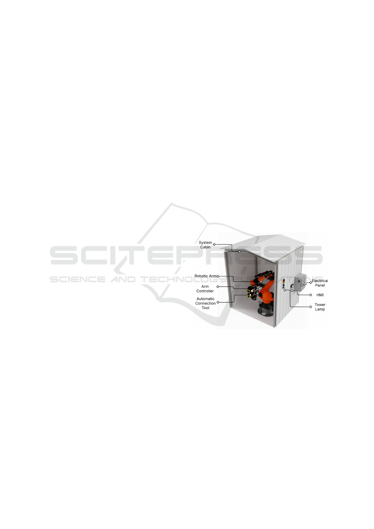
The proposed autonomous robotic fueling system,
shown in Figure 1, is designed to optimize refueling
for mining dump trucks in open-pit environments. It
connects and disconnects the fuel nozzle in approx-
imately 56 seconds, improving efficiency and reduc-
ing downtime. Compared to Pitstop, which requires
75 seconds for connection and 30 seconds for discon-
nection (Rotec, 2025), the proposed system reduces
total fueling time by nearly 33%, further enhancing
operational performance.
A key component is the robotic arm, which pro-
vides extended reach, high precision, and repeatabil-
ity. To ensure reliability in harsh mining conditions,
it is enclosed in a protective cabin that shields it from
dust, debris, and extreme temperatures. Structural
components are made of stainless steel 304, offering
high resistance to corrosion and mechanical wear, en-
hancing durability and operational lifespan.
This section details the robotic arm configuration
and its controller, followed by the mechanical and
electronic design of the automatic connection tool for
precise fuel nozzle attachment. The electrical panel
design is then examined, covering energy supply, con-
trol, data processing, and communication. Finally, the
monitoring interface and signaling systems that en-
sure operational safety are introduced.
Figure 1: Perspective-isometric view of the Automated Fu-
eling System.
3.1 Robotic Arm Configuration
The selection of the robotic arm was based on an
analysis of dimensional reach and load capacity re-
quirements. A reach of 2902 mm was determined af-
ter evaluating various dump truck models, ensuring a
minimum safety distance. The estimated load capac-
ity, based on the preliminary design of the connection
tool, was approximately 60 kg.
Given these requirements, the KUKA KR-120
3100 F was chosen for its ability to meet both reach
and load demands. Its foundry configuration en-
sures reliable operation in harsh environments, fea-
turing IP65 protection for the structure and IP67 at
Design of an IoT-Driven Software Architecture for an Automated Robotic Fueling System in Open-Pit Mining
457
the end effector, providing resistance to dust and wa-
ter ingress. With a repeatability of ±0.05 mm, it deliv-
ers consistent performance over prolonged operations
and across large fleets.
The arm is managed by the KR-C5 control sys-
tem, housed in a Basic Cab configuration, enabling
full operational control.
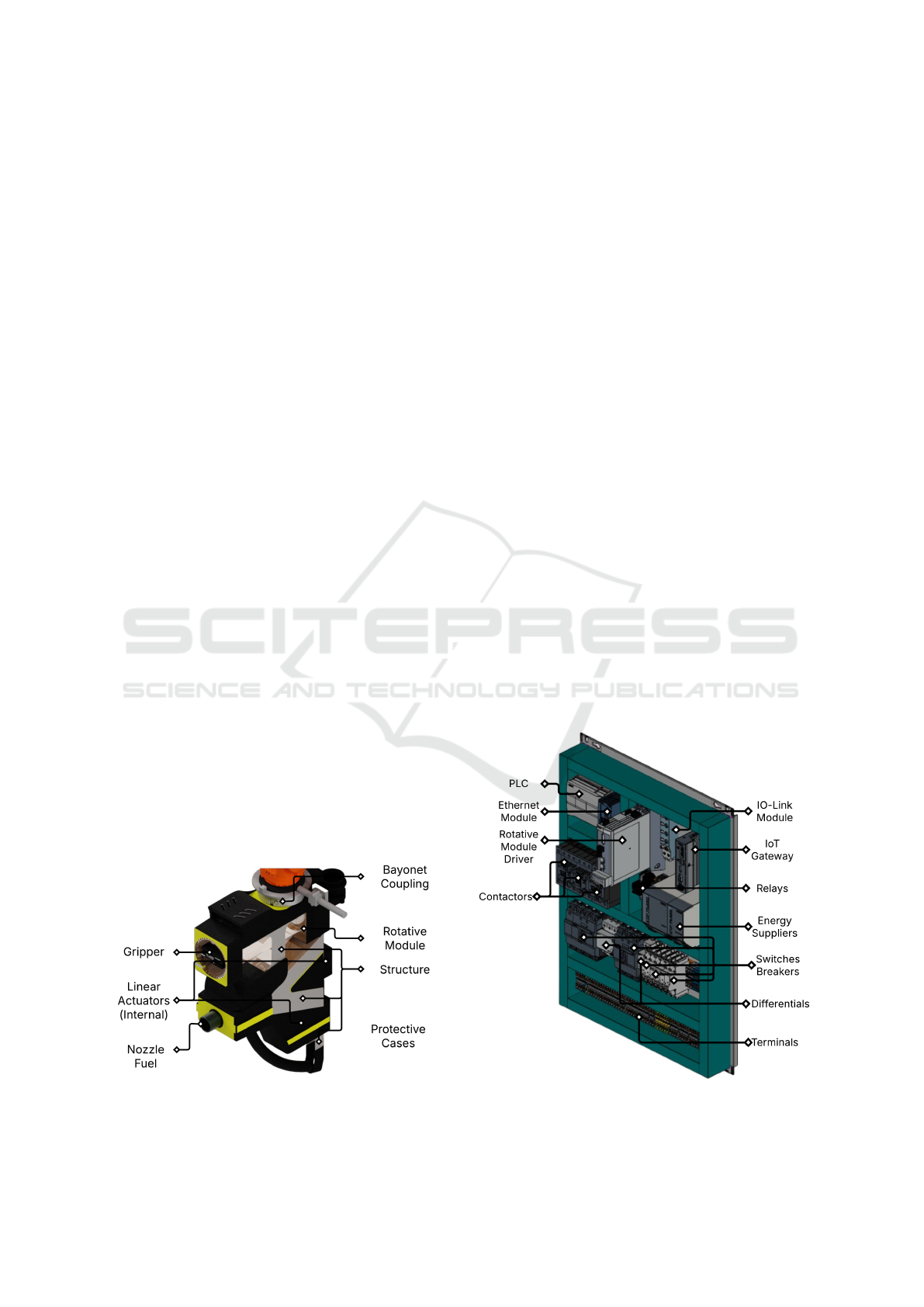
3.2 Automatic Connection Tool
An automatic connection tool, shown in Figure 2, was
designed to ensure a precise and reliable connection
between the fuel nozzle and the fuel tank.
At the core of the system’s automated position-
ing is a 3D vision system with high spatial resolu-
tion, operating alongside an industrial PC responsi-
ble for processing tank cap position calculations via a
pose estimation algorithm. Image data is transferred
at high speed using 10GigE Ethernet technology, en-
abling computations in under 2 seconds. The pro-
cessed spatial data is then sent to the robotic controller
for precise tool positioning.
The connection process follows three distinct
phases to ensure accuracy and efficiency. In the first
phase, a gripper secures the fuel tank’s screw cap
while a rotary module applies the required torque for
removal. In the second phase, the fuel nozzle is posi-
tioned using a linear actuator, which moves it 50 mm
horizontally along precision-guided ball rails. The fi-
nal phase initiates fuel flow by lifting the nozzle lever
with another linear actuator, supported by an inter-
nally designed mechanism. Disconnection follows
the same sequence in reverse.
To protect internal components, a robust protec-
tive casing shields the tool from dust, moisture, and
mechanical impacts, ensuring durability in harsh en-
vironments. Finally, the tool is securely attached to
the robotic arm’s end effector using a bayonet cou-
pling, enabling quick and reliable installation.
Figure 2: Isometric view of the Automatic Connection Tool.
3.3 Electrical Panel
The electrical panel, illustrated in Figure 3, is housed
in a protective enclosure (600×800×400 mm) and
contains the essential components for energy protec-
tion, control, supply, data processing, and communi-
cation.
For energy protection, the panel includes differ-
ential and circuit breakers, ensuring safe power dis-
tribution across the system with 40 A, 20 A, 10 A,
and 6 A outputs. Energy control and supply are man-
aged using industrial contactors and regulated power
supplies, delivering stable power to DC devices, in-
cluding linear actuators.
A programmable logic controller (PLC) governs
system operation, managing control via I/O interfaces
and Ethernet ports. Relay outputs are connected to
intermediary relays for safe contactor control, while
dedicated inputs handle start, stop, and emergency
stop functions. The panel also houses a servo drive,
responsible for regulating the rotary module.
For connectivity and expandability, the panel in-
tegrates an Ethernet switch, allowing the PLC to ex-
pand its network connections. An IO-Link module
connects components such as the gripper and tower
lamp, while an industrial IoT gateway centralizes data
for cloud processing.
The panel is designed for an organized layout,
incorporating structured wiring distribution and ded-
icated terminal blocks for earth, neutral, and relay
connections, ensuring efficient operation and mainte-
nance.
Figure 3: Internal isometric view of the Electrical Panel.
IoTBDS 2025 - 10th International Conference on Internet of Things, Big Data and Security
458

3.4 Monitoring and Signaling
Process data, including fuel level, filling velocity, user
information, and operational stage, is displayed on
a human-machine interface (HMI), allowing the fuel
station operator to monitor fueling in real-time. The
HMI communicates with the PLC via an Ethernet
connection, ensuring accurate process tracking and
seamless data exchange.
System status signaling is managed by a tower
lamp, which provides visual and auditory alerts
throughout the fueling process. The lamp emits inter-
mittent lighting and audible alarms to indicate system
operation and is controlled by the PLC via an IO-Link
interface, ensuring timely and reliable signaling.
4 CLOUD-PLATFORM
SOLUTION DESIGN
The development of the system requires a platform
capable of monitoring the entire operation in real
time. This is achieved through the design of a cloud
platform architecture that leverages Internet of Things
(IoT) sensors integrated into the system. The design
process is carried out using the ADD 3.0 methodol-
ogy, which is structured into seven systematic steps.
Before initiating the design process, it is necessary to
define the architectural drivers, including use cases,
quality attributes, architectural constraints, and ar-
chitectural concerns, as a foundational prerequisite
(L
´
opez et al., 2021; Ruiz-Navarro et al., 2021).
4.1 Architectural Drivers
User cases
The functional requirements represent the specific
capabilities or functionalities that the system must de-
liver. These requirements are defined and detailed
through use cases, as outlined in Table 1.
Quality Attributes
These are measurable characteristics of interest to
users that define how effectively the system performs
its functions. They are outlined in Table 2.
Architectural Constraints
These are restrictions or limitations imposed on
the architecture. Constraints may arise from business
decisions, regulatory requirements, or legacy systems.
In this design process, they primarily reflect technical
choices, as presented in Table 3.
Architectural Concerns
These represent the interests, needs, and expec-
tations of all stakeholders involved in the system, as
outlined in Table 4.
Table 1: Use Case Description.
ID User Case Description
UC-1
Authenticate
User
The user authenticates in
the system to access the
functions of the
automated system.
UC-2
Start Filling
Cycle
The truck operator starts
the fuel filling cycle in
the system.
UC-3
Stop Filling
Cycle
The truck operator stops
the fuel filling cycle
upon completing the
process or in case of
emergency.
UC-4
Record
Incident
The operator or the
system records an
incident occurring
during the filling or
maintenance process.
UC-5
Generate
Automatic
Mainte-
nance
The system detects and
automatically schedules
maintenance based on
incidents or alerts
generated during the
filling cycle.
UC-6
Generate
Manual
Mainte-
nance
The administrator or
station supervisor can
manually create a
maintenance request for
the equipment or
system.
UC-7
Generate
Operation
Report
The system generates a
detailed report of
operations, including
fillings, incidents, and
recorded maintenances.
4.2 Design Process
The previously defined architectural drivers are used
to iteratively design the architecture, as outlined in the
following sections.
4.2.1 Architectural Priorities: Input Review,
Goal Definition, and Element Selection
Following the ADD 3.0 methodology, the initial steps
establish a solid architectural foundation. Step 1 re-
views and validates architectural drivers to ensure
alignment with system objectives. Step 2 defines the
iteration’s goal, addressing all drivers to finalize the
architecture in a single cycle. Step 3 selects and
refines key components, ensuring the architecture is
fully developed within this iteration.
Design of an IoT-Driven Software Architecture for an Automated Robotic Fueling System in Open-Pit Mining
459
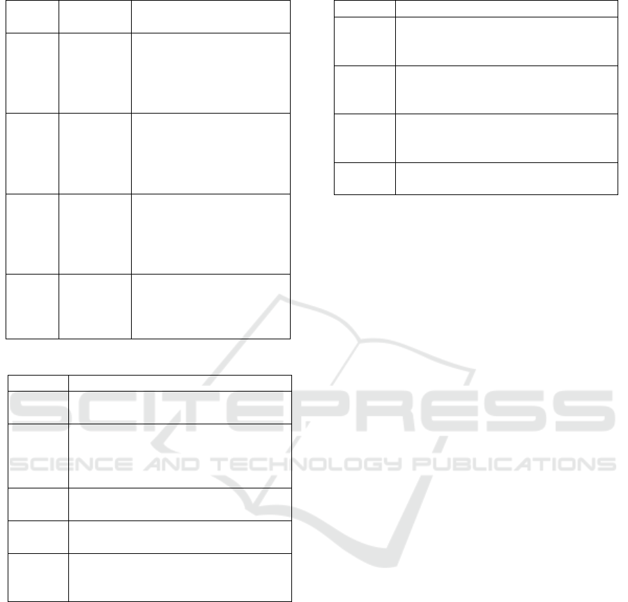
Table 2: Quality Attributes Scenarios.
ID
Quality
Attribute
Scenario
QA-1 Security
A user attempts to access
the system without valid
credentials, and the
system denies access
100% of the time.
QA-2 Reliability
The operator wants to
manually record an
incident, and the system
generates it correctly
100% of the time.
QA-3 Reliability
The system automatically
generates a maintenance
request correctly 100%
of the time when there is
a critical system incident.
QA-4 Reliability
The administrator
generates a maintenance
request correctly 100%
of the time.
Table 3: System Constraints.
ID Constraint
CON-1
Use AWS as the cloud service
provider for the deployment model.
CON-2
Access to the monitoring system
must be through a web browser
using a device connected to the
mine’s Wi-Fi network.
CON-3
Use a communication protocol
oriented to IoT.
CON-4
Use an IoT-oriented reference
architecture based on AWS services.
CON-5
Use a relational database for
compatibility with the mine’s
database.
4.2.2 Design Concept Selection to Satisfy
Architectural Driverss
As part of step 4, the architectural design and host-
ing decisions follow an IoT service-oriented archi-
tecture optimized for real-time monitoring and con-
trol. Sensor data is collected through a robust con-
trol system, processed efficiently, and displayed via
a user-friendly web application while generating de-
tailed incident logs during fuel-filling operations. To
meet these requirements, the following AWS-based
services were selected:
Smart Farm on AWS Reference Architecture
(AWS, 2024a) was selected for its IoT compatibil-
Table 4: System Concerns.
ID Concern
CRN-1
Ensure compatibility with existing
equipment and technology in the
mining environment.
CRN-2
Design the system based on
modularity criteria to facilitate
updates and maintenance.
CRN-3
Ensure proper management of
incident records for compatibility
with the mine’s database.
CRN-4
Ensure real-time information
processing.
ity (CON-3), seamless AWS integration, and real-
time processing (CRN-4). Its modular design en-
sures interoperability with mining equipment (CRN-
1) and simplifies maintenance (CRN-2). It also pro-
vides secure access control (QA-1) and reliable in-
cident logging with automated maintenance (QA-2,
QA-3). Alternatives like Siemens Industrial Edge
on AWS (AWS, 2024b), Connected Restaurants Us-
ing IoT, AI & ML (AWS, 2022), and Edge Inference
for Agriculture (AWS, 2020) were discarded due to
misalignment with fuel monitoring, unnecessary edge
processing, and higher costs.
Edge Computing minimizes latency by process-
ing data locally, enabling real-time monitoring and in-
stant responses to critical events (UC-2, UC-3, UC-
4). It leverages IoT protocols (CON-3) and integrates
with AWS IoT Greengrass (CON-4) for scalable, ro-
bust processing.
IoT Device Management Platform enables
seamless cloud connectivity, real-time data exchange,
and efficient incident management. It supports pre-
dictive maintenance, device configuration, and diag-
nostics to ensure operational continuity (UC-4, UC-
5). Compliant with IoT protocols (CON-3), it lever-
ages AWS IoT Core for centralized management
(CON-4).
Data Storage securely manages incident logs,
sensor data, and reports, ensuring scalability and
accessibility for analysis (UC-4, UC-7). AWS S3
provides cost-efficient storage while complying with
AWS security protocols (CON-1).
Data Visualization Tools provide intuitive inter-
faces for analyzing operational data, improving sys-
tem health and performance insights (UC-7). AWS
QuickSight powers dynamic dashboards for action-
able decision-making (CON-1).
Event-Driven Code Execution automates actions
like maintenance alerts and safety responses (UC-4,
UC-5). AWS Lambda ensures efficient, reliable event
processing (CON-1, CON-3).
IoTBDS 2025 - 10th International Conference on Internet of Things, Big Data and Security
460

Centralized Security Alerts coordinate re-
sponses to security threats, protecting system access
and data (UC-1, CON-2). AWS IoT Device Defender
monitors and mitigates vulnerabilities.
Real-Time Notifications alert users about inci-
dents and maintenance needs, ensuring prompt re-
sponses and operational efficiency (UC-4, UC-6).
AWS SNS guarantees reliable, immediate message
delivery (CON-1).
Application Programming Interface (API)
Communication Interface enables secure, reliable
integration between the web application and backend
services (UC-1, UC-2, UC-6). It adheres to indus-
try standards and ensures consistent data exchange via
Wi-Fi (CON-2).
A relational Cloud Database Service was selected
to ensure compatibility with the mine’s existing re-
lational database (CON-5). This choice enables
structured management of incident logs and opera-
tional data, ensuring integrity and consistency (CRN-
3). The cloud-based approach provides scalability,
high availability, and fault tolerance, supporting real-
time processing and seamless integration with local
databases (CRN-4). A secure endpoint will facili-
tate reliable data exchange between the cloud and on-
premise infrastructure via the system’s API.
4.2.3 Instantiation of Architectural Elements
As part of step 5, the following design decisions in-
stantiate the architectural elements to meet system re-
quirements.
AWS IoT Greengrass enables local machine
learning and data processing, collecting sensor data
and responding to critical events in real time. This
minimizes latency and reduces dependency on con-
stant server connectivity (UC-2, UC-3, UC-4). It ad-
heres to IoT protocols (CON-3), integrates with AWS
architecture (CON-4), and ensures reliability and se-
curity (QA-2, QA-3).
AWS IoT Core manages IoT devices and com-
munication via MQTT, ensuring reliable data trans-
mission for incident detection and management (UC-
4, UC-5). It complies with IoT protocols (CON-3),
integrates with AWS architecture (CON-4), and pri-
oritizes reliability and security (QA-2, QA-3).
Amazon S3 securely stores incident logs, reports,
and maintenance records, ensuring scalable and ac-
cessible data management (UC-4, UC-7). It complies
with AWS restrictions (CON-1) and Wi-Fi access
(CON-2), prioritizing security and reliability (QA-
1). Amazon QuickSight provides interactive visual-
izations for data-driven decision-making (UC-7), ad-
hering to AWS restrictions (CON-1) and ensuring re-
liability (QA-2).
AWS Lambda automates critical tasks by pro-
cessing sensor data, detecting incidents, and trigger-
ing maintenance (UC-4, UC-5). It retrieves and pre-
pares data from the mine database via API Gateway,
ensuring seamless integration for analysis and visu-
alization. This service adheres to AWS standards
(CON-1), supports IoT protocols (CON-3), and en-
hances reliability and security (QA-2, QA-3).
AWS Security Hub centralizes security alerts,
protecting against unauthorized access and ensuring
data integrity (UC-1). It complies with Wi-Fi secu-
rity protocols (CON-2) and prioritizes robust security
measures (QA-1).
Amazon SNS delivers real-time notifications to
users about incidents or maintenance, improving op-
erational response times (UC-4, UC-6). This service
adheres to AWS restrictions (CON-1), emphasizing
reliability and security (QA-1, QA-3).
Amazon API Gateway ensures secure, efficient
communication between the web application, back-
end services, and the mine database via a dedi-
cated endpoint. It enables seamless access to sys-
tem functionalities (UC-1, UC-2, UC-6) with secure
Wi-Fi connectivity (CON-2) while ensuring real-time
data availability (CRN-4) and compatibility (CON-
5). Acting as a secure intermediary, it facilitates ef-
ficient data exchange between local and cloud-based
systems.
AWS DynamoDB was chosen for its compatibil-
ity with the mine’s database (CON-5) and efficient in-
cident management (CRN-3). Its scalability ensures
real-time processing and peak performance (CRN-
4). Integration with AWS Lambda and IoT Core en-
hances reliability (QA-2, QA-4), while its NoSQL ar-
chitecture enables flexible data storage.
4.2.4 Design Visualization and Evaluation
Upon completing the previous steps, step 6 illustrates
the final architecture in Figure 4. In step 7, a com-
prehensive evaluation of steps 1 to 6 confirmed that
the established goal was successfully achieved. This
iteration effectively addressed the primary functional-
ities, quality attributes, architectural constraints, and
concerns, ensuring the completeness of the cloud plat-
form architecture design process. For brevity, the
Kanban board has been omitted.
5 INTEGRATION
The AWS-based cloud architecture enables real-time
monitoring of the automated fueling process, integrat-
ing the physical system, data sources, and end users
Design of an IoT-Driven Software Architecture for an Automated Robotic Fueling System in Open-Pit Mining
461
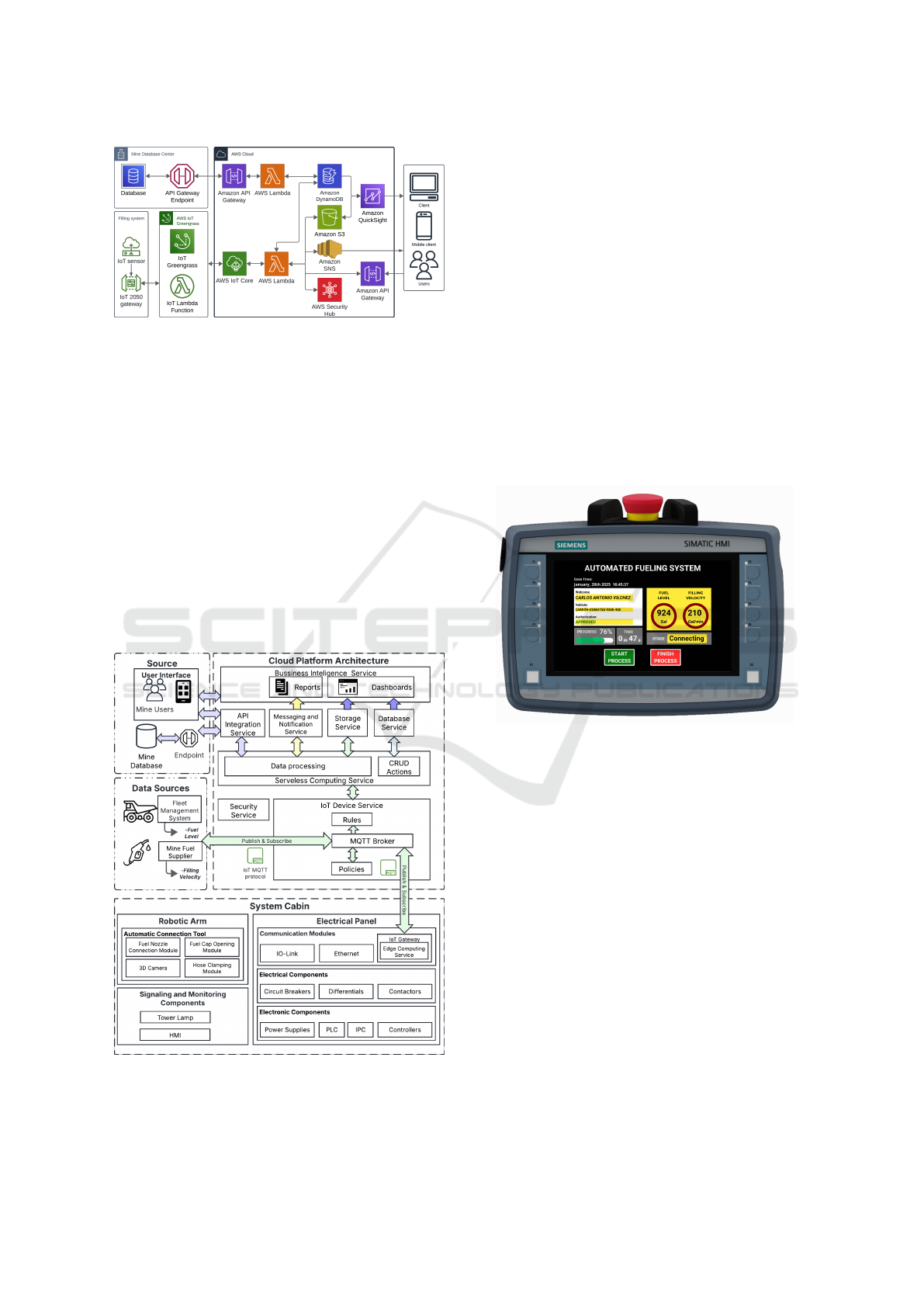
Figure 4: Cloud-Platform architecture diagram.
through IoT technology. As illustrated in Figure 5,
data from the fleet management system and fuel sup-
pliers is transmitted via IoT MQTT protocols to the
cloud, where it is processed, stored, and made avail-
able for analysis. The system connects to a central-
ized mine database through an API integration ser-
vice, ensuring secure data retrieval and storage.
Mine operators can access the system via a dedi-
cated user interface, which provides real-time insights
through reports and dashboards generated by the busi-
ness intelligence service. This interface allows users
to monitor fueling operations, track key performance
indicators, and respond to alerts efficiently.
Inside the system cabin, the robotic arm, electri-
cal panel, and monitoring components operate in syn-
chronization to optimize fueling.
Figure 5: System Integration Diagram.
6 INTERFACE PROTOTYPING
Following the design process, the prototyping phase
focused on developing user interfaces for the auto-
mated fueling system, accessible via the SIMATIC
KTP700 Mobile HMI and a responsive web applica-
tion.
The HMI interface (Figure 6) provides on-site op-
erators with real-time data, including credentials, ve-
hicle ID, fuel level, fill velocity, and process status.
Intuitive action buttons streamline operation, mini-
mizing errors.
The web application offers remote access from
mobile and desktop devices, mirroring HMI func-
tionalities such as authorization status, vehicle de-
tails, and process tracking. Cloud integration ensures
secure, real-time synchronization, enabling fueling
management from any location.
Figure 6: HMI interface Mockup.
7 CONCLUSIONS
This paper presents the design of an automated
robotic fueling system for haul trucks in open-pit min-
ing, addressing inefficiencies in the manual fueling
process. The proposed system automates key tasks
such as fuel nozzle positioning, authorization, and
process monitoring, improving operational efficiency
and reducing downtime.
The system design integrates IoT technology
and a cloud-based platform, ensuring seamless com-
munication between physical components and data
sources. The implementation of the VDI 2206
methodology for the physical system and ADD 3.0
methodology for the cloud platform enabled a struc-
tured and scalable approach. The developed interface
prototypes, including an HMI and a responsive web
application, provide operators with real-time monitor-
ing and control capabilities, enhancing usability and
IoTBDS 2025 - 10th International Conference on Internet of Things, Big Data and Security
462

accessibility.
As a next step, future work should focus on the
implementation of the cloud platform to validate the
proposed ADD 3.0 design and assess its performance
in real-world conditions. Further enhancements, such
as predictive maintenance integration, could improve
system reliability and scalability.
Overall, the proposed system demonstrates a vi-
able solution for optimizing fueling operations in
mining environments, offering potential for broader
industrial applications.
REFERENCES
Auto-Energy (2022). Automatic refueling technology.
https://autoenergy.se/products/fuelmatics/.
Autofuel (2024). Automatic refueling. https://autofuel.eu/.
AWS (2020). Edge Inference for Agri-
culture. https://d1.awsstatic.com/
architecture-diagrams/ArchitectureDiagrams/
edge-inference-for-agriculture-ra.pdf?did=wp card&
trk=wp card.
AWS (2022). Connected Restaurants using
IoT and AI/ML. https://d1.awsstatic.com/
architecture-diagrams/ArchitectureDiagrams/
connected-restaurants-using-iot-ai-ml-ra.pdf?did=
wp card&trk=wp card.
AWS (2024a). Farm on Amazon Web Services.
https://docs.aws.amazon.com/architecture-diagrams/
latest/smart-farm-on-aws/smart-farm-on-aws.html.
AWS (2024b). Integrate Siemens Industrial Edge
with AWS IoT Sitewise. https://d1.awsstatic.
com/architecture-diagrams/ArchitectureDiagrams/
siemens-industrial-edge-on-aws-ra.pdf.
Bi, Z., Luo, C., Miao, Z., Zhang, B., and Zhang,
C. W. J. (2021). Automatic robotic recharging
systems – development and challenges. Indus-
trial Robot, 48(1):95–109. https://doi.org/10.1108/
IR-05-2020-0109.
Censtar Science & Technology Corp ltd (2024). Auto-
matic robot refueling device and refueling method
(CN114195083A). https://patents.google.com/patent/
CN114195083A/en.
Cervantes, H. and Kazman, R. (2024). Designing software
architectures: a practical approach. Addison-Wesley
Professional.
Gausemeier, J. and Moehringer, S. (2002). VDI 2206- A
New Guideline for the Design of Mechatronic Sys-
tems. IFAC Proceedings Volumes, 35(2):785–790. 2nd
IFAC Conference on Mechatronic Systems, Berkeley,
CA, USA, 9-11 December.
Guo, L., Liu, K., Zhang, L., Zhang, Y., Tian, Y., and Zhang,
J. (2021). Research on vision perception technol-
ogy of auto fueling robot on opencv-based gas tank
cap recognition. Journal of Physics: Conference
Series, 1952(2):022067. https://dx.doi.org/10.1088/
1742-6596/1952/2/022067.
Hazakhstan Robotics Zhongshan Co Ltd (2022). Au-
tomatic refueling equipment and automatic refu-
eling system for automobile (CN111573608A).
https://patents.google.com/patent/CN111573608A/
en?oq=CN111573608A.
Hollerback, J. A. (2013). Automated vehicle fuel-
ing apparatus and method (US8393362B1).
https://patents.google.com/patent/US8393362B1/
en?oq=US8393362B1#citedBy.
Lam, C. T. and Phung, T. C. (2021). Research on applica-
tion of industrial robots in automated fueling systems
for small individual cars. VNUHCM Journal of Engi-
neering and Technology, 4(3):1057–1067.
L
´
opez, F. M. S., Delgado, J. M. P., De la Cruz, E. G. S.,
and C
´
aceres, E. L. (2021). Performance-based soft-
ware architecture design and blockchain as a service
for peruvian e-government. In 2021 IEEE 12th In-
ternational Conference on Software Engineering and
Service Science (ICSESS), pages 1–5. IEEE.
MINEM (2024). Actualizaci
´
on de la cartera de
proyectos de inversi
´
on minera. https://www.
gob.pe/institucion/minem/informes-publicaciones/
5374641-boletin-estadistico-minero-enero-2024.
Pouresmaieli, M., Ataei, M., and Taran, A. (2022). Future
mining based on internet of things (iot) and sustain-
ability challenges. International Journal of Sustain-
able Development & World Ecology, 30(2):211–228.
https://doi.org/10.1080/13504509.2022.2137261.
Quiquia, M. and William, G. (2015). Mejoramiento con-
tinuo en la gesti
´
on del ciclo de acarreo de camiones
en miner
´
ıa a tajo abierto en Antamina, Cerro Verde,
Toquepala, Cuajone, Yanacocha, Alto Chicama, Las
Bambas, Cerro Corona, Antapacay y Pucamarca. http:
//hdl.handle.net/20.500.14076/2181.
Rotec (2025). Robotic fuelling system for haul
trucks, mining trucks, trains and agvs.
https://rotec-engineering.nl/robotic-fuelling-systems/
robotic-fuelling-system-for-haul-trucks/.
Ruiz-Navarro, J. A., Santos-L
´
opez, F. M., Portella-Delgado,
J. M., and Santos-de-la Cruz, E. G. (2021). Computer
vision technique to improve the color ratio in estimat-
ing the concentration of free chlorine. In Interna-
tional Conference on Computer Science, Electronics
and Industrial Engineering (CSEI), pages 127–141.
Springer.
Scott Automation (2023). https://scottautomation.com/en-
us/products/mining/mining-field-
automation/robofuel.
Stratom (2024). Rapid refueling, recharging and liq-
uid transfer system. https://www.stratom.com/
rapid-stratoms-autonomous-refueling-recharging-and
-liquid-transfer-system/.
Walter, M., De Pi
´
erola, J. C., Cooper, C., Zegarra, D.,
Diez Canseco, C., Gobitz, V., Laguna, R., and Liendo,
C. (2021). Miner
´
ıa en Per
´
u 2021-2030:¿ Qu
´
e rol juega
en la reactivaci
´
on econ
´
omica y el desarrollo territorial.
Estudio y recomendaciones sectoriales. Banco Inter-
americano de Desarrollo.
Design of an IoT-Driven Software Architecture for an Automated Robotic Fueling System in Open-Pit Mining
463
